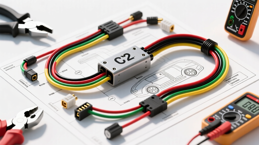
The Diagnostic Value of a Custom Wiring Diagram Extension Cord
When diagnosing complex powertrain management systems, technicians frequently need to intercept sensor signals without damaging the original equipment manufacturer (OEM) harness. Piercing wires with T-taps or test-light probes compromises the waterproof seals and invites copper oxidation, leading to catastrophic CAN-bus or sensor failures. A properly constructed wiring diagram extension cord—often referred to as a diagnostic breakout harness—serves as a sacrificial bridge. By referencing the factory service manual, you can fabricate a custom extension cord that plugs directly into the OEM connector and the sensor, exposing raw wire lengths for safe oscilloscope back-probing and multimeter testing.
From a cost and tool requirements perspective, building your own harnesses offers immense advantages over purchasing proprietary OEM breakout boxes. This analysis breaks down the capital expenditure for tools, the material costs per harness, and the exact technical specifications required to build a reliable 4-Pin Heated Exhaust Gas Oxygen (HEGO) sensor extension cord.
Tool Requirements & Capital Expenditure Analysis
Fabricating automotive-grade harnesses requires specialized tooling to ensure gas-tight crimps and environmental sealing. According to the SAE J1128 Standard for low-tension primary cable, terminal retention and crimp compression must meet strict pull-test and electrical resistance thresholds. Using hardware store crimpers will result in cold crimps that fail under engine bay vibration and thermal cycling.
Essential Crimping and Stripping Tools
- Wire Strippers: Knipex 12 40 200 Precision Strippers ($45). Essential for stripping 22-18 AWG without nicking the copper strands, which reduces ampacity and creates fatigue points.
- Crimping Tool: TE Connectivity CERTI-CRIMP II or equivalent ratcheting crimper ($180 - $250). Ratcheting crimpers ensure the terminal is compressed to the exact factory specification, creating a cold-weld, gas-tight seal that prevents moisture intrusion.
- Terminal Insertion Tool: Deutsch/TE Connectivity insertion and extraction wedges ($15). Prevents bending the terminal locking tangs when seating pins into the connector housing.
Soldering and Diagnostic Accessories
- Soldering Station: Weller WECP-20 or Hakko FX-888D ($100 - $150). While crimping is the primary mechanical bond, soldering the wire-to-terminal barrel adds a secondary environmental seal against high-heat zones like exhaust manifolds.
- Heat Gun: Steinel HL 2020 E ($60). Required for shrinking dual-wall, adhesive-lined polyolefin heat shrink tubing to waterproof the harness.
- Back-Probe Pins: Fluke TP810 or equivalent thin-profile back-probes ($25). Allows oscilloscope testing at the extension cord's exposed junction without spreading the OEM connector terminals.
Material Cost Breakdown: DIY vs. OEM Breakout Boxes
Dealership-specific breakout boxes (such as those from Ford Rotunda or GM Kent-Moore) typically cost between $120 and $250 per sensor type. By utilizing a wiring diagram extension cord methodology, you can build application-specific harnesses for a fraction of the cost.
| Component | OEM Breakout Box | DIY Extension Cord |
|---|---|---|
| Connector Pigtails (Male/Female) | Included ($0) | $12.00 (OEM Dealer Pigtail) |
| Wire (PTFE & TXL Spec) | Included ($0) | $4.50 (Mil-Spec PTFE/TXL) |
| Heat Shrink & Loom | Included ($0) | $2.00 (Adhesive-Lined) |
| Terminal Pins (If not using pigtail) | N/A | $1.50 (TE Connectivity) |
| Total Estimated Cost | $150.00 - $250.00 | $18.50 - $20.00 |
For high-volume diagnostic shops, the initial capital expenditure of $400+ for professional crimping tools is recouped after building just three or four custom extension harnesses.
Technical Blueprint: 4-Pin HEGO Sensor Extension
To build a functional wiring diagram extension cord, you must adhere to the specific wire gauge and insulation material requirements dictated by the sensor's operating environment. The 4-Pin Narrowband Heated Oxygen Sensor is a universal standard across most OBD-II vehicles. The signal wires require low-dielectric, high-melting-point insulation, while the heater circuit requires higher ampacity.
| Pin | Function | Standard Color | AWG Size | Insulation Material |
|---|---|---|---|---|
| 1 | Signal Output (Nernst Cell) | White / Black | 22 AWG | PTFE (Tefzel) |
| 2 | Signal Ground / Low | Grey / White | 22 AWG | PTFE (Tefzel) |
| 3 | Heater Power (12V Switched) | Red / Black-White | 18 AWG | TXL (Cross-Linked) |
| 4 | Heater Ground (PCM Controlled) | Black / White-Black | 18 AWG | TXL (Cross-Linked) |
Note: Always verify wire colors against the specific vehicle's wiring diagram extension cord schematic, as OEM color codes vary between manufacturers (e.g., Ford vs. GM vs. Toyota). The AWG and material specs, however, remain constant for safety and signal integrity.
Step-by-Step Fabrication and Cost Optimization
- Acquire OEM Pigtails: Instead of buying loose terminals and attempting to weather-seal them manually, purchase a male and female OEM pigtail from the dealer or a trusted supplier like TE Connectivity. This guarantees the connector locking tangs and silicone weather seals are factory-perfect.
- Cut and Strip: Cut your PTFE and TXL wire to a length of 18 inches. Strip 5mm of insulation. PTFE requires sharp, precision strippers as the insulation is tough and tends to stretch rather than cut.
- Crimp and Solder: If using loose terminals, crimp the wire barrel using the ratcheting crimper. For extreme heat zones (within 6 inches of the exhaust manifold), flow a small amount of 63/37 rosin-core solder into the wire barrel. Do not solder the insulation barrel, as this creates a rigid stress point that will snap under engine vibration.
- Seal and Protect: Slide 3/16" dual-wall adhesive heat shrink over every individual wire splice. The inner adhesive layer melts and flows into the wire strands, creating a waterproof barrier against road salt and engine degreasers. Bundle the harness in split loom or high-temperature fiberglass sleeving.
Troubleshooting Signal Degradation in Extension Harnesses
When integrating a custom wiring diagram extension cord into a diagnostic workflow, technicians may encounter signal anomalies if the harness is built improperly. Below are common failure modes and their engineered solutions.
Symptom: Erratic O2 Voltage Switching or Noise
- Cause: Electromagnetic Interference (EMI) from adjacent ignition coil wires or fuel injector circuits coupling into the high-impedance Nernst cell signal wires.
- Fix: Ensure the 22 AWG PTFE signal wires (Pins 1 and 2) are twisted together at a rate of 4 to 6 twists per inch. Twisting the wires cancels out induced common-mode noise. Never run signal wires parallel to high-current ignition harnesses.
Symptom: Heater Circuit DTC (e.g., P0135 / P0141)
- Cause: Voltage drop across the extension cord. If a technician mistakenly uses 22 AWG wire for the heater circuit (Pins 3 and 4), the resistance of the extended wire length will cause a voltage drop, preventing the PCM from detecting the expected current draw (typically 1.5A to 2.5A).
- Fix: Strictly adhere to the 18 AWG TXL specification for the heater circuit. If the extension cord exceeds 24 inches in length, upgrade the heater circuit to 16 AWG to compensate for resistance over distance.
Symptom: Melted Insulation Near Exhaust
- Cause: Use of standard PVC primary wire (GPT) instead of PTFE or TXL. Standard PVC insulation melts at approximately 105°C (221°F), which is easily exceeded near the catalytic converter.
- Fix: PTFE (Tefzel) withstands continuous temperatures up to 200°C (392°F) and resists soldering iron burns during fabrication. Always verify the wire jacket material before routing the extension cord near the exhaust manifold.
Conclusion
Constructing a custom wiring diagram extension cord is a highly cost-effective alternative to purchasing single-use OEM breakout boxes. By investing in professional-grade crimping tools and utilizing Mil-Spec PTFE and TXL wiring, technicians can fabricate durable, signal-accurate diagnostic harnesses for under $20 each. This approach not only protects the vehicle's expensive OEM wiring harness from invasive probing but also elevates the accuracy of oscilloscope and live-data diagnostics.
For further reading on wideband sensor architectures and advanced pinouts, refer to the Bosch Motorsport LSU Documentation to adapt these fabrication techniques for 5-pin and 6-pin wideband extension cords.