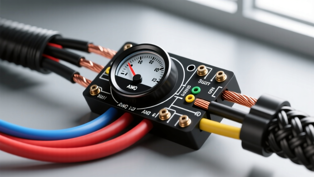
Understanding Ammeter Topologies in Automotive Electrical Systems
When integrating an aftermarket instrument cluster or restoring an OEM dashboard, understanding the correct wiring diagram for amp gauge configurations is critical for both measurement accuracy and vehicle fire prevention. Unlike a voltmeter, which merely samples system voltage via a light-gauge sense wire, an ammeter measures the actual current flow (in Amperes) moving between the alternator and the battery. Depending on the era and design of the vehicle, this requires routing either the entire electrical output of the charging system through the dashboard (Series/Loop type) or utilizing a remote shunt with low-current signal wires (Shunt/Hall-Effect type).
This technical reference outlines the exact specifications, wire gauges, terminal types, and routing protocols for both topologies, ensuring your installation meets rigorous automotive electrical standards.
Series (Loop-Type) Amp Gauge Wiring Diagram & Specifications
In a traditional series ammeter setup—commonly found in classic muscle cars, early trucks, and hot rods (e.g., 1960s-1980s GM, Ford, and Mopar platforms)—the gauge acts as a literal bridge in the main charging circuit. All current produced by the alternator that is not immediately consumed by the vehicle's electrical loads must pass directly through the ammeter to reach the battery. Because modern 1-wire or high-output alternators can produce 100 to 140+ amps, the wiring diagram for amp gauge setups of this type demands heavy-duty cabling and strict safety protocols.
Standard Series Routing Path
- Alternator BAT Terminal: The main charging wire originates here.
- Fusible Link / Mega Fuse: A protective device must be installed within 7 inches of the alternator output to prevent catastrophic harness fires in the event of a dead short.
- Ammeter Post A (Input): The heavy-gauge wire routes through the firewall to the first gauge stud.
- Ammeter Post B (Output): A second heavy-gauge wire routes back through the firewall to the battery positive terminal or starter solenoid main post.
Table 1: Series Ammeter Hardware & Wire Sizing Matrix
| Alternator Output Rating | Minimum Wire Gauge (AWG) | Terminal Type | Stud Torque Spec | Fusible Link Rating |
|---|---|---|---|---|
| Up to 60 Amps (e.g., GM 10SI) | 10 AWG (Primary) / 8 AWG (Recommended) | M8 (5/16") Ring Terminal, Adhesive Heat Shrink | 45 - 55 in-lbs | 14 AWG Fusible Link (Rated ~24A continuous blow) |
| 61 - 100 Amps (e.g., GM 12SI, Ford 2G) | 8 AWG (Primary) / 6 AWG (Recommended) | M8 (5/16") Ring Terminal, Adhesive Heat Shrink | 55 - 65 in-lbs | 12 AWG Fusible Link |
| 101 - 140+ Amps (e.g., 1-Wire, 3G, CS144) | 4 AWG (Minimum) | M8 (5/16") Ring Terminal, Anti-Oxidant Paste Required | 65 - 75 in-lbs | 150A ANL Fuse or 10 AWG Fusible Link |
Expert Note: According to MAD Enterprises, routing 100+ amps through a dashboard-mounted series ammeter is inherently dangerous due to the resistance and heat generated at the gauge studs. For alternators exceeding 80 amps, converting to a shunt-type ammeter or a high-resolution voltmeter is strongly advised.
Shunt-Type (Hall-Effect) Amp Gauge Wiring Diagram
Modern high-performance vehicles, marine applications, and updated classic car restomods utilize a shunt-type or Hall-effect ammeter. In this configuration, the heavy main charging current completely bypasses the dashboard. Instead, a remote shunt block or Hall-effect sensor is installed in the engine bay, directly on the main battery cable. The gauge in the dashboard only receives low-current millivolt signals, drastically reducing the risk of dashboard fires and voltage drop.
Shunt Installation & Signal Routing
The main battery cable (typically 1/0 AWG or 2/0 AWG) is cut and routed through the remote shunt block. Two or three small-gauge signal wires are then routed through the firewall to the back of the dashboard ammeter. These signal wires measure the voltage drop across the internal resistor of the shunt (typically 50mV at full scale) or read the magnetic field in a Hall-effect sensor.
Table 2: Shunt Ammeter Signal Pinout & Wire Specifications
| Gauge Pin | Wire Color (Standard Aftermarket) | Function | Wire Gauge | Connection Point |
|---|---|---|---|---|
| Pin 1 (SIG+) | Red with White Tracer | Shunt Positive Signal Input | 18 AWG (Shielded/Twisted Pair) | Shunt Block Terminal A |
| Pin 2 (SIG-) | Black with White Tracer | Shunt Negative Signal Input | 18 AWG (Shielded/Twisted Pair) | Shunt Block Terminal B |
| Pin 3 (PWR) | Solid Red | Switched 12V+ Ignition Source | 16 AWG | Fuse Box (IGN Circuit, 5A Fuse) |
| Pin 4 (GND) | Solid Black | Chassis / Dash Ground | 16 AWG | Clean Bare Metal Dash Frame |
When routing the 18 AWG signal wires, it is imperative to twist the SIG+ and SIG- wires together (at least 4 twists per foot) to reject Electromagnetic Interference (EMI) generated by the alternator stator, ignition coils, and EFI fuel injectors. Failure to twist these signal wires will result in erratic gauge needle flutter at idle.
Critical Safety Protocols and Fusible Link Integration
The most common failure mode associated with the series wiring diagram for amp gauge setups is the "ammeter fire." This occurs when the nuts on the back of the gauge studs vibrate loose over time. The resulting high-resistance connection generates immense heat, melting the plastic dashboard housing and igniting the insulation of the main harness. To mitigate this, adherence to SAE J1128 standards for low-tension primary cable and battery wire is mandatory.
- Hardware Selection: Never use standard zinc-plated steel nuts on ammeter studs. Always use copper or brass nuts with a Star-Lock washer or a Nord-Lock wedge-locking washer to prevent vibration-induced loosening.
- Dielectric Protection: Coat the bare copper strands and the crimped terminal barrel with an anti-oxidant compound (such as Noalox) before crimping to prevent galvanic corrosion, which increases resistance over time.
- Firewall Pass-Through: Heavy 8 AWG or 4 AWG wires passing through the firewall must utilize a rubber grommet or a dedicated firewall bulkhead connector. Bare wires rubbing against sheet metal will eventually short to ground, bypassing the gauge entirely and causing a meltdown.
- Upgrading to Voltmeters: If your vehicle utilizes a high-output alternator (100A+) but retains a factory series ammeter, the safest technical modification is to bypass the ammeter entirely using a heavy-gauge jumper wire, and install a separate voltmeter to monitor system health. Painless Performance Products highly recommends this topology for modern engine swaps into classic chassis.
Diagnostic Troubleshooting Matrix
Use the following decision tree to diagnose common amp gauge anomalies based on the specific wiring topology you are utilizing.
| Symptom | Topology | Probable Cause | Diagnostic Fix / Verification |
|---|---|---|---|
| Gauge reads zero at all times, but battery is charging. | Series | Main charging wire is routed directly to battery, bypassing the gauge. | Verify alternator BAT wire routes to Gauge Post A, and Gauge Post B routes to Battery/Solenoid. |
| Gauge pegs hard to DISCHARGE under heavy load. | Series | Wires on Post A and Post B are reversed. | Swap the heavy-gauge wires on the back of the gauge studs. Polarity dictates charge/discharge direction. |
| Needle flutters erratically at idle, stabilizes at high RPM. | Shunt | EMI interference on signal wires or poor chassis ground. | Ensure SIG+ and SIG- are twisted pair. Verify Pin 4 ground has less than 0.05V drop to battery negative. |
| Gauge reads CHARGE continuously, even with engine off. | Shunt | Pin 3 (PWR) wired to constant 12V instead of switched IGN. | Move Pin 3 power source to a fuse panel circuit that is only live in IGN or RUN positions. |
| Dashboard smells like melting plastic; gauge studs are hot. | Series | Loose terminal nuts causing high resistance and arcing. | IMMEDIATELY disconnect battery. Clean studs, apply anti-oxidant paste, and torque to spec with Nord-Lock washers. |
Final Verification Steps
After completing the wiring diagram for amp gauge installation, perform a load test. Turn on the vehicle's headlights, HVAC blower motor on high, and rear defroster. With the engine idling, the ammeter should show a slight discharge or neutral state. When the engine is revved to 1,500 RPM, the gauge should immediately swing to the CHARGE side, indicating the alternator has taken over the electrical load and is replenishing the battery. Use a digital multimeter (DMM) across the battery terminals to corroborate the ammeter's behavior; you should see voltage climb from ~12.6V (engine off) to 13.8V - 14.4V (engine running).