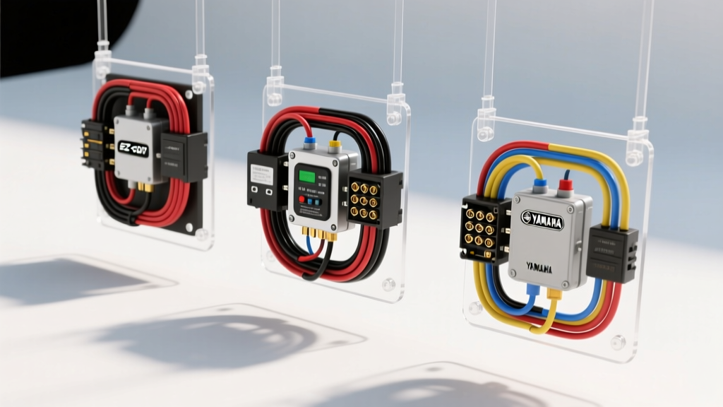
The Big Three: Comparing Golf Cart Wiring Diagrams & Architectures
When sourcing golf cart wiring diagrams for repair, restoration, or performance upgrades, technicians quickly realize that the 'Big Three' manufacturers—Club Car, EZ-GO, and Yamaha—utilize vastly different electrical architectures. Selecting the correct wiring schematic, harness kit, and diagnostic manual requires a deep understanding of these platform-specific nuances. Whether you are troubleshooting a 36V series-wound DC system or upgrading to a 72V lithium-powered AC setup, this product comparison and selection guide will help you navigate the wiring ecosystems of the Club Car Precedent IQ, EZ-GO RXV, and Yamaha Drive (G29).
Club Car Precedent IQ (48V DC Architecture)
The Club Car Precedent IQ system relies on a 48V DC series-wound motor and a proprietary V-Glide or MCOR (Motor Controller Output Regulator) throttle input. The wiring diagrams for the IQ system are heavily focused on the solenoid pre-charge circuit and the Forward/Reverse (F&R) microswitch assembly. Unlike older resistor-coil speed controllers, the IQ utilizes a solid-state MOSFET controller. A critical component in the IQ wiring diagram is the 470-ohm, 2-watt pre-charge resistor (or diode, depending on the exact year) wired across the solenoid's high-amperage terminals. This prevents the controller's main capacitors from drawing a massive inrush current that would weld the Albright SW180 solenoid contacts shut.
EZ-GO RXV (48V AC Architecture)
EZ-GO revolutionized the market with the RXV by eliminating the traditional mechanical solenoid and F&R switch, opting instead for a 48V AC induction motor paired with a Curtis Instruments 1354 AC controller. The RXV wiring diagrams are defined by 3-phase motor cabling (U, V, W) and a solid-state main contactor integrated directly into the controller's logic board. The F&R function is handled electronically via a 3-position toggle switch sending 12V logic signals to the controller's J3 connector. When selecting RXV wiring harnesses, you must prioritize shielded, high-flex silicone cables for the 3-phase AC outputs to prevent electromagnetic interference (EMI) with the Hall-effect throttle sensor.
Yamaha Drive G29 (DC & AC Variants)
Yamaha's G29 (Drive) platform bridges the gap between traditional DC and modern AC systems. Early G29 models utilized a Yamaha-branded DC motor with a mechanical sliding-block F&R switch that actuates dual microswitches. Later models transitioned to AC systems. Yamaha wiring diagrams are notorious for their complex regenerative braking circuits and proprietary multi-pin connectors. When selecting a wiring manual for a G29, ensure it specifically matches the motor type (DC vs. AC), as the controller pinouts and main harness routing are entirely incompatible between the two.
Wiring Harness & Cable Selection Guide
Choosing the correct aftermarket wiring harness or building a custom loom requires strict adherence to amperage ratings and voltage drop limits. Standard OEM harnesses often use 2 AWG or 4 AWG cable, which is sufficient for stock 300A controllers but inadequate for upgraded 600A+ performance setups. According to SAE J1128 standards for battery cables, selecting the proper AWG is critical to prevent voltage sag and insulation melting under peak load.
| Circuit Application | System Voltage | Peak Amperage | Recommended AWG | Insulation / Connector Type |
|---|---|---|---|---|
| Main Battery to Controller (DC) | 48V / 72V | 400A - 800A | 1/0 AWG or 2/0 AWG | EPDM Rubber / 3/8" Ring Terminals |
| Controller to Motor (AC Phase U,V,W) | 48V AC | 300A - 500A | 2 AWG (High Flex) | Silicone / M8 Ring or Deutsch DT |
| Battery Interconnects (Series) | 8V / 12V links | System Peak | 2/0 AWG (Custom cut) | Lead-Antimony / BCI Standard Lugs |
| Solenoid Coil / Logic Power | 12V / 48V | 2A - 5A | 14 AWG | PVC / 1/4" Spade Terminals |
| Throttle / Hall-Effect Sensors | 5V Reference | < 1A | 18 AWG (Shielded) | Silicone / AMP Superseal 1.2mm |
| Accessories (Lights, Horn, USB) | 12V (via reducer) | 10A - 20A | 12 AWG to 14 AWG | PVC / ATC Fuse Holders |
Controller Pinouts & Connector Selection
A major point of failure in golf cart electrical systems is the degradation of OEM plastic connectors. When replacing a harness or reading a wiring diagram to bypass a faulty plug, upgrading the connector type is highly recommended.
EZ-GO RXV Curtis 1354 Throttle Pinout (J3 Connector)
The RXV uses a Hall-effect throttle pedal assembly. The OEM connector is prone to moisture ingress. When selecting a replacement pigtail, opt for an AMP Superseal 1.2mm 3-pin waterproof connector.
- Pin 1 (Red): 5V Reference from Controller
- Pin 2 (White/Green): Signal Return (Sweeps 0.8V at idle to 3.6V at WOT)
- Pin 3 (Black): Sensor Ground
Club Car Precedent IQ MCOR Pinout
The MCOR (Motor Controller Output Regulator) replaced the older V-Glide potentiometer. It uses a proprietary 4-pin Molex-style connector. If sourcing an aftermarket adapter harness, ensure the pin spacing matches the Molex MX150 standard.
- Pin 1 (Yellow): 15V Reference
- Pin 2 (Blue): Wiper / Throttle Signal (0.8V to 3.2V sweep)
- Pin 3 (Black): Ground
- Pin 4 (Green): Microswitch Input (Foot brake interlock)
Selecting the Right Diagram Manual & Diagnostic Tools
Not all wiring diagrams are created equal. When selecting a service manual for your cart, you must choose between OEM Dealer PDFs, aftermarket printed guides, and interactive diagnostic software.
OEM Dealer Schematics (Best for Pinpoint Diagnostics)
OEM diagrams (available through Club Car, EZ-GO, and Yamaha dealer portals) are the gold standard. They include exact wire color codes, routing clips, and proprietary connector part numbers. However, they are often locked behind dealer login portals. Independent shops typically purchase annual subscriptions to aggregator services that host these OEM PDFs.
Aftermarket Harness Kits with Laminated Schematics
For DIYers, purchasing a premium aftermarket wiring harness kit (such as those from Royall or Navitas) often includes a laminated, color-coded wiring diagram specific to the harness. These are superior to generic internet PDFs because they reflect the exact color codes of the aftermarket wires, which rarely match the faded OEM factory colors.
Interactive Diagnostic Software
For modern AC carts (RXV and newer Club Car Onward models), static PDF diagrams are insufficient. Selecting a Bluetooth diagnostic tool (like the Navitas app or Curtis 1311 handset) provides real-time 'live' wiring diagrams. These tools highlight the exact pin on the screen that is currently receiving voltage, acting as a dynamic wiring schematic that eliminates the need to trace physical wires with a multimeter.
Troubleshooting Common Wiring Failures
Use this decision tree to diagnose common electrical faults based on your specific cart's wiring architecture:
Symptom: Solenoid Clicks, But Cart Does Not Move
- Club Car IQ: Check the F&R microswitches. The wiring diagram shows that the controller will not output PWM to the motor unless the F&R switch completes the 15V logic circuit. Use a multimeter to verify continuity on the Red/White wire when the shifter is in Forward.
- EZ-GO RXV: The RXV has no traditional solenoid 'click' for the motor phase. If the main contactor engages but the cart is dead, check the 3-phase AC cables (U, V, W). A broken crimp on one phase will cause the Curtis controller to throw an HPD (High Pedal Disable) or Phase Fault code.
Symptom: Intermittent Power Loss Under Heavy Load
- All Models: This is almost always a voltage drop issue caused by undersized battery interconnect cables or corroded ring terminals. Refer to the AWG chart above. If you are running 22-inch tires on a lifted cart, the increased rolling resistance draws higher amperage. Upgrade the main battery cables from OEM 4 AWG to 1/0 AWG silicone welding cable to eliminate voltage sag.
- Club Car Precedent: Inspect the pre-charge resistor. If the 470-ohm resistor is cracked or burnt, the controller capacitors will draw massive inrush current, causing the B+ and B- terminals on the controller to overheat and intermittently shut down the system.
Upgrading to Lithium & High-Amperage Harnesses
When converting a lead-acid golf cart to a 48V or 72V Lithium-Ion battery (such as Allied or EcoBattery), the wiring diagram changes significantly at the main battery disconnect. Lithium BMS (Battery Management Systems) require a dedicated communication wire (CAN bus or RS485) routed to the charger and sometimes the controller. When selecting a lithium conversion harness, ensure it includes shielded twisted-pair (STP) cabling for the CAN bus lines to prevent the high-frequency PWM noise from the motor controller from corrupting the BMS data, which can cause the battery to unexpectedly shut off mid-drive.