Adapting Residential Hydronics for Expedition Vehicles and RVs
Custom motorhomes, skoolies, and overland expedition trucks increasingly rely on hydronic heating systems to maintain interior temperatures and prevent underbelly wet-bays from freezing. While marine and RV-specific 12V DC valves exist, many master fabricators prefer the reliability, brass construction, and high-flow Cv ratings of residential HVAC components. Consequently, engineers and custom builders frequently search for a wiring diagram for taco zone valve components when designing these complex wet-bay systems. The Taco 571-X2 series, a 24VAC synchronous motor zone valve, is the industry standard for these builds due to its quiet operation and robust auxiliary end-switches.
However, integrating a 24VAC residential component into a 12V DC or 24V DC vehicle house electrical system requires precise voltage conversion, relay isolation, and adherence to automotive wiring standards. This technical specification reference provides the exact schematics, AWG requirements, and multiplex integration strategies needed to wire a Taco zone valve into an RV or expedition vehicle safely and effectively.
Core Electrical Architecture: 12V DC to 24V AC Conversion
Vehicle house banks typically operate at 12V DC (or 24V DC in heavy-duty expedition chassis). The Taco 571 series requires 24VAC to actuate the synchronous motor and open the valve. Direct DC application will instantly destroy the motor coil. Therefore, the primary architectural requirement is a dedicated step-up transformer or a DC-to-AC inverter sized specifically for inductive HVAC loads.
Transformer Sizing and Inrush Current Management
The Taco 571-X2 zone valve exhibits an inrush current of approximately 0.80 Amps at 24VAC when the thermostat first calls for heat, dropping to a holding current of 0.30 Amps once the valve is fully open. In a multi-zone RV setup (e.g., separate zones for the bedroom, living area, and wet-bay floor heat), multiple valves may open simultaneously.
- Single Zone Setup: Requires a minimum 20VA transformer (24VAC output).
- Multi-Zone Setup (3-4 Valves): Requires a 40VA to 50VA transformer to prevent voltage sag during simultaneous inrush events.
For the 12V DC primary side of the transformer, you must use an isolated DC-to-AC power supply designed for automotive environments, such as the Victron Energy Orion series or a dedicated 12V-to-120V pure sine inverter paired with a standard 40VA HVAC doorbell transformer. Always fuse the 12V DC primary feed at 150% of the maximum continuous draw using an automotive ATC blade fuse or MegaFuse, depending on the amperage.
Step-by-Step Wiring Diagram for Taco Zone Valve (3-Wire Configuration)
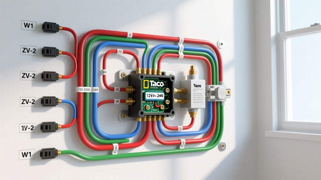
The standard Taco 571-X2 utilizes a 3-wire configuration for the motor and an additional 3-wire configuration for the auxiliary end-switch. Below is the logical flow for the motor control circuit.
- Thermostat Call: The 12V DC RV thermostat (e.g., Micro-Air EasyTouch or a standard 24VAC Nest powered by the transformer) closes the circuit, sending 24VAC to the valve.
- Motor Actuation: 24VAC enters Terminal 1 of the Taco valve. The current passes through the synchronous motor and exits via Terminal 2, returning to the transformer common.
- End-Switch Engagement: As the valve gear rotates to the open position, a microswitch engages. This bridges Terminal 1 (Common) and Terminal 2 (Normally Open) on the auxiliary switch block, signaling the vehicle's PLC or circulator pump relay to turn on.
Terminal Block Pinout and Wire Color Codes
When routing wires through an RV chassis or skoolie floor, always use SAE J1128 compliant stranded, tinned copper wire to resist vibration and oxidation. Do not use solid core residential Romex wire in any vehicle application, as chassis flex will cause the copper to fatigue and snap.
| Component Terminal | Function | Wire Color (RV Standard) | AWG Size (Stranded Tinned) |
|---|---|---|---|
| Transformer Hot (24VAC) | Power Feed to Thermostat | Red | 18 AWG |
| Thermostat Output | Switched 24VAC to Valve | White | 18 AWG |
| Taco Valve Terminal 1 (Motor) | 24VAC Input | White (from T-Stat) | 18 AWG |
| Taco Valve Terminal 2 (Motor) | 24VAC Common Return | Blue | 18 AWG |
| Transformer Common (24VAC) | System Ground / Neutral | Blue | 18 AWG |
Integrating the End-Switch with Vehicle Multiplex Systems
In advanced expedition vehicles, the Taco valve's auxiliary end-switch is not just used to turn on a 120V circulator pump; it is integrated into the vehicle's 12V DC multiplex system (such as VECAN, NMEA 2000, or a custom Arduino/Raspberry Pi node) to monitor valve status and trigger Webasto or Espar coolant pumps.
To bridge the 24VAC end-switch to a 12V DC vehicle logic controller, you must use an isolated automotive relay. A standard Bosch-style 5-pin relay (e.g., Bosch 0 332 209 150) is ideal for this isolation.
- Relay Pin 86 (Coil +): Connected to a 12V DC ignition or house-bank switched source.
- Relay Pin 85 (Coil -): Connected to Taco Auxiliary Terminal 2 (Normally Open).
- Taco Auxiliary Terminal 1 (Common): Connected to Vehicle Chassis Ground.
- Relay Pin 30 (Common): Connected to 12V DC Logic Feed.
- Relay Pin 87 (Normally Open): Connected to the RV Multiplex Digital Input Node.
When the Taco valve opens, the auxiliary switch closes, grounding Pin 85 of the relay. The relay coil energizes, and Pin 87 sends a 12V signal to the multiplex node, confirming the valve is open and instructing the main hydronic boiler to fire.
Troubleshooting Common RV Voltage Drop Failures
The most common failure mode when adapting a wiring diagram for taco zone valve setups in long-wheelbase vehicles (like Sprinter vans or 40-foot Class A motorhomes) is voltage drop on the 24VAC secondary side. The Taco synchronous motor requires a minimum of 20VAC to generate enough torque to open the valve against the hydraulic pressure of the glycol mixture.
Diagnostic Decision Tree
- Symptom: Valve hums but fails to open, or opens intermittently.
- Test: Measure AC voltage directly at the transformer secondary terminals while the thermostat is calling for heat. (Expected: 24VAC - 26VAC).
- Test: Measure AC voltage at Taco Terminals 1 and 2 while under load. (Expected: >22VAC).
- Fix: If voltage at the valve is below 22VAC, the 18 AWG wire run is too long. Upgrade the 24VAC trunk line to 16 AWG or 14 AWG stranded tinned copper to reduce resistance over long chassis runs.
- Symptom: Valve opens, but the multiplex system never registers the end-switch signal.
- Test: Use a digital multimeter in continuity mode across Taco Auxiliary Terminals 1 and 2. Manually rotate the valve gear with the manual open lever. (Expected: Continuity beep when fully open).
- Fix: If continuity exists but the relay doesn't trigger, check for a floating ground on the 12V DC relay coil circuit. Ensure the vehicle chassis ground is bonded to the house-bank negative busbar per RVIA (RV Industry Association) electrical standards.
Authoritative References and Best Practices
When designing and executing vehicle-specific hydronic integrations, always refer to the manufacturer's baseline specifications and automotive wiring standards:
- Taco HVAC 571 Zone Valve Product Data Sheet: Provides the exact inrush amperage, torque ratings, and auxiliary switch wiring schematics necessary for transformer sizing.
- SAE J1128: Low Tension Primary Cable: The governing standard for wire insulation thickness, temperature ratings, and stranded copper requirements in mobile and vehicular environments.
- RV Industry Association (RVIA) Electrical Standards: Dictates proper overcurrent protection, fuse sizing, and chassis grounding protocols for 12V DC and converted AC systems in motorized recreational vehicles.
By strictly adhering to these wire color codes, AWG specifications, and relay isolation techniques, you ensure that your vehicle's hydronic heating system operates flawlessly, whether parked in a sub-zero alpine environment or navigating rough corrugated backroads.