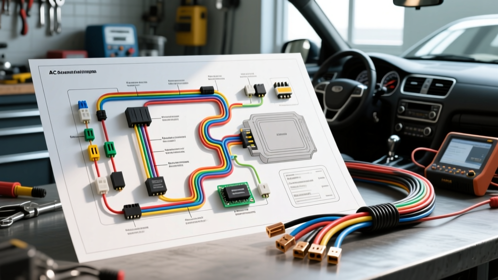
The High Cost of Ignoring the Schematic
When diagnosing a failed mobile air conditioning (MAC) system, many technicians and DIYers rely on guesswork, swapping relays and jumping wires without consulting the factory documentation. However, a proper wiring diagram of air conditioning system circuits is not just a map of electrical flow; it is a critical safety document. Misinterpreting this schematic on modern vehicles—specifically those utilizing Powertrain Control Module (PCM) integrated low-side drivers—can result in catastrophic component failure, refrigerant explosions, or severe personal injury.
In this guide, we will dissect the most common and costly mistakes made when reading and testing automotive AC circuits, using the highly prevalent GM GMT800 platform (1999-2006 Silverado/Sierra 4.8L/5.3L) as our technical baseline. By understanding the precise wire color codes, AWG ratings, and control logic, you can diagnose AC failures safely and accurately.
Anatomy of the AC Clutch Control Circuit
Before identifying mistakes, we must establish the baseline circuit logic. In the GMT800 platform, the AC compressor clutch is not engaged by a simple 12V switch on the dashboard. The HVAC control module sends a request signal to the PCM. The PCM then verifies engine load, coolant temperature, and refrigerant pressure switch status before completing the ground path for the AC clutch relay coil.
Common Mistake #1: Backprobing the PCM Driver Directly
The most destructive mistake occurs when a technician attempts to test the control side of the AC clutch relay by probing the PCM control wire with a standard 12V test light or by applying a 12V jumper wire. According to Haynes Automotive Electrical Basics, modern PCMs utilize internal quad-drivers (low-side switches) to control relays. The PCM does not supply 12V+ to the relay coil; it supplies the ground path.
If you apply external 12V+ to the PCM control wire (Dark Green/White on the GMT800, Pin 42 of Connector C1), you will instantly short the circuit through the PCM's internal transistor, permanently destroying the driver and requiring a full PCM replacement. Always use a high-impedance digital multimeter (DMM) or a logic probe rated for computer-controlled circuits when testing the control side of the diagram.
Common Mistake #2: Bypassing the Binary/Ternary Pressure Switch
A frequent, highly dangerous error is jumping the AC pressure switch connector to force the compressor to engage. The wiring diagram of air conditioning system layouts clearly shows the pressure switch (often a binary or ternary switch located on the accumulator or high-pressure line) acting as a series interrupt for the PCM request signal or relay coil feed.
If a system is low on R134a refrigerant, the low-pressure side of the switch opens at approximately 22-28 PSI. This is designed to prevent the compressor from running without adequate lubrication, as PAG oil is suspended in the refrigerant. Bypassing this switch will cause the compressor to seize, sending shrapnel through the entire AC system (the dreaded 'Black Death'). Conversely, if the high-pressure side is bypassed while the condenser is restricted, pressures can exceed 450 PSI, leading to a catastrophic hose rupture or compressor explosion. SAE J1995 standards for System Integrity strictly mandate that these safety cut-outs must never be defeated.
Common Mistake #3: Confusing Relay Coil Pins with Load Pins
Standard ISO micro-relays use specific pin numbering. Pin 85 and 86 represent the electromagnetic coil (control circuit), while Pins 30 and 87 represent the high-amperage load circuit (clutch feed). A common mistake is misreading the schematic and testing the 14 AWG Orange battery feed wire (Pin 30) expecting to see PCM switching logic. The PCM only interacts with the 18 AWG control wires. Mixing these up leads to hours of misdiagnosis and potential short circuits.
GMT800 AC Clutch Wire Specifications and Pinout Reference
The following table details the exact specifications for the GM GMT800 AC compressor clutch circuit. Use this as a reference when probing the underhood electrical center (fuse block) and PCM connectors.
| Circuit Function | Wire Color | AWG Size | Connector / Pin Location | Voltage State (Key On, AC Off) |
|---|---|---|---|---|
| Relay Load Feed (Battery) | Orange | 14 AWG | Relay Pin 30 | 12V+ Constant |
| Clutch Feed (Load Output) | Light Green/Black | 14 AWG | Relay Pin 87 to Clutch | 0V (12V+ when engaged) |
| Relay Coil Feed (Ignition) | Dark Green/White | 18 AWG | Relay Pin 86 | 12V+ (Ignition On) |
| Relay Coil Ground (PCM) | Black/White | 18 AWG | Relay Pin 85 to PCM C1-42 | 12V+ (Drops to <1V when engaged) |
| AC Request Signal (HVAC to PCM) | Tan/White | 20 AWG | PCM C1-43 | 0V (Rises to 12V on AC Request) |
Critical Safety Warnings: High Voltage, Moving Parts, and Refrigerant
When working with the wiring diagram of air conditioning system components, electrical safety is only half the battle. You are simultaneously dealing with high-pressure thermodynamics and heavy rotating mechanical assemblies.
- Mechanical Entanglement Hazard: Never probe the AC clutch electrical connector with the engine running and the serpentine belt installed unless absolutely necessary. If your test light or jumper wire accidentally completes the circuit, the clutch will engage instantly. Fingers, loose clothing, or testing leads caught in the pulley gap will result in severe amputation or degloving injuries.
- Refrigerant Exposure: According to EPA Section 609 Technician Certification guidelines, R134a and R1234yf refrigerants displace oxygen and can cause severe frostbite upon contact with skin or eyes. Never disconnect a pressure switch or service port without first verifying system pressure with a manifold gauge set. If the system is fully charged, removing the binary switch will release refrigerant violently.
- Short Circuit Fire Risk: The 14 AWG Orange feed wire to the AC relay is often tied directly to the battery or a high-amperage ignition bus. If you pierce this wire with a test probe and it touches the chassis ground, it can draw over 40 amps instantly, melting the probe and potentially starting an underhood fire. Always use proper back-probing pins at the connector rather than piercing wire insulation.
Diagnostic Decision Tree: Compressor Clutch Won't Engage
Follow this logical sequence derived from the factory schematic to isolate the fault without risking PCM damage:
- Verify Refrigerant Pressure: Connect manifold gauges. Ensure static pressure is above 45 PSI. If below 28 PSI, the low-pressure switch is open. Recharge system; do not bypass switch.
- Check Relay Load Circuit: With the engine off, remove the AC clutch relay. Use a fused jumper wire between Relay Pins 30 and 87 in the fuse block. If the clutch clicks and engages, the 14 AWG Light Green/Black wire and clutch coil (typically 3.5 - 4.5 ohms) are intact. If not, check the clutch air gap (should be 0.020' - 0.030').
- Check Relay Coil Feed: Key On, Engine Off. Probe Relay Pin 86 (Dark Green/White). You must read battery voltage (12V+). If 0V, check the HVAC fuse and ignition feed circuit.
- Verify PCM Request & Ground: Reinstall relay. Connect a DMM to Relay Pin 85 (Black/White). Turn on the AC to MAX. The voltage should drop from 12V to less than 1.0V. If it stays at 12V, the PCM is not providing the ground. Scan the PCM for 'AC Request' status. If the scanner shows 'Yes' but no ground is present, the PCM internal driver is likely open (failed). If scanner shows 'No', diagnose the HVAC control head, ambient temperature sensor, or high-pressure switch circuit.
Conclusion
Treating a wiring diagram of air conditioning system layouts as a mere suggestion is a fast track to destroyed control modules and unsafe vehicle operation. By respecting the low-side driver logic of the PCM, honoring the physical safety barriers of the pressure switches, and utilizing the correct AWG-rated testing procedures, you ensure both your safety and the longevity of the vehicle's MAC system. Always verify your schematic against the specific RPO codes and model year of your vehicle before applying power to any circuit.