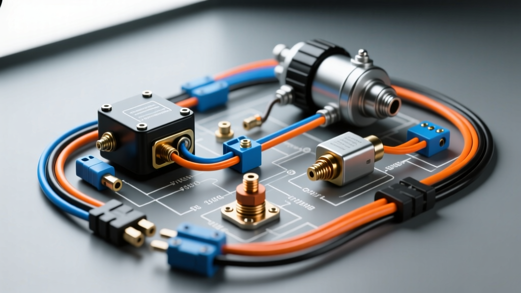
Introduction to High-Amperage Horn Circuits
Installing a train horn kit—whether it is a Nathan AirChime replica or a genuine VIAIR 480C dual-compressor system—demands strict adherence to high-amperage DC circuit protocols. A standard automotive horn draws 10 to 15 amps, but a heavy-duty train horn compressor can pull 30 amps continuously and spike over 60 amps during startup. Routing this current through a standard dashboard switch will result in melted insulation, severe voltage drop, and catastrophic electrical fires. This comprehensive train horn wiring diagram and installation guide details the exact relay logic, AWG requirements, and termination methods required for a safe, professional-grade installation on any 12-volt automotive or light-truck electrical system.
Core Electrical Specifications and AWG Requirements
Before cutting into your vehicle’s harness, you must size your wires and overcurrent protection devices correctly. According to SAE J1128 standards for low-tension primary cable, wire gauge must be selected based on maximum continuous amperage and total circuit length to prevent a voltage drop exceeding three percent. Furthermore, all under-hood wiring must meet cross-linked polyethylene (XLPE) insulation standards to withstand 125-degree Celsius ambient temperatures near the engine bay. To maintain standard automotive color codes, use Red for primary 12V+ feeds, Black for chassis grounds, and Yellow for low-amperage trigger circuits.
| Circuit Function | Wire Gauge (AWG) | Wire Color | Fuse Rating | Connector Type |
|---|---|---|---|---|
| Battery to Main Relay (Pin 30) | 8 AWG | Red | 60A ANL / Class-T | 3/8 in. Ring Terminal |
| Relay to Compressor (Pin 87) | 10 AWG | Red | 40A Inline AGU | Weather-Pack / Ring |
| Relay Trigger (Pin 85) | 16 AWG | Yellow | 5A Mini Fuse | Spade / T-Tap |
| Relay Ground (Pin 86) | 16 AWG | Black | None (Chassis) | Ring Terminal (1/4 in.) |
| Solenoid Valve Actuation | 14 AWG | Red/Black | 10A Inline ATC | Deutsch DT Series |
The Master Train Horn Wiring Diagram Breakdown
A professional train horn installation utilizes three distinct circuits: the high-amperage compressor feed, the solenoid valve actuation, and the low-amperage control trigger. We utilize a heavy-duty 12V 60A sealed automotive relay to isolate the high current from the driver’s cabin.
Circuit 1: Compressor Power and Relay Control
The heart of the train horn wiring diagram relies on a standard 5-pin or 4-pin Bosch-style relay. For high-amperage compressor loads, a sealed Metri-Pack 280 or Weather-Pack relay is preferred over unsealed spade terminals to prevent corrosion.
- Pin 30 (Power Input): Run 8 AWG primary wire directly from the positive battery terminal to Pin 30. You must install a 60A ANL or Class-T fuse within 18 inches of the battery positive post. This protects the main feed in the event of a dead short. Torque the battery ring terminal to 10 Nm (7.4 lb-ft) to prevent micro-arcing.
- Pin 87 (Normally Open Output): Run 10 AWG wire from Pin 87 to the positive terminal of the air compressor. If you are running dual compressors, split this circuit using a sealed distribution block, maintaining 10 AWG to each compressor head.
- Pin 85 (Trigger Input): Run 16 AWG wire from your dashboard-mounted momentary switch. The switch should receive switched 12V power from an accessory fuse tap (e.g., a 5A mini-fuse on the ignition circuit).
- Pin 86 (Ground): Ground this pin directly to a clean, bare-metal chassis point using a 16 AWG black wire and a ring terminal.
Expert Tip: Because the relay coil is an inductive load, collapsing the magnetic field when you release the horn button creates a voltage spike (inductive kickback). Solder a 1N4001 flyback diode across Pins 85 and 86 (stripe facing Pin 85) to protect your dashboard switch and vehicle ECU from voltage transients.
Circuit 2: Solenoid Valve Actuation
Train horns require a massive, instantaneous volume of air, which is delivered by a 12V air solenoid valve (such as a MAC valve or VIAIR 1/2-inch port valve). Do not wire the solenoid directly to the compressor power feed. The solenoid must be triggered independently by the horn button. Wire the solenoid valve using 14 AWG wire, protected by a 10A inline AGU fuse. The horn button acts as the ground trigger or positive trigger for a secondary 30A relay dedicated to the solenoid. Using a secondary relay ensures the horn button only handles milliamps of current, extending the lifespan of the switch. Connect the solenoid negative to the chassis and the positive to the relay output.
Circuit 3: Pressure Switch Integration
To prevent compressor burnout and tank over-pressurization, a pressure switch (e.g., VIAIR 90220, set to 150 PSI on and 200 PSI off) must be integrated into the compressor control circuit. The most reliable method is to wire the pressure switch in series with the relay ground. Route the 16 AWG ground wire from Relay Pin 86 through the pressure switch before terminating at the chassis ground. When the air tank reaches 200 PSI, the switch opens, breaking the ground path and shutting off the compressor relay, regardless of whether the dashboard switch is engaged.
Termination, Routing, and Environmental Protection
The most common failure point in aftermarket accessory wiring is poor termination. Never use twist-on wire nuts or solder-only connections in high-vibration automotive environments. According to Delphi and Littelfuse connection guidelines, you must use open-barrel crimp terminals with the correct die size for your AWG wire. For 8 AWG and 10 AWG power wires, use adhesive-lined dual-wall heat shrink over your ring terminals to create a watertight seal. Apply dielectric grease to all relay spades and solenoid connectors to prevent galvanic corrosion. Route all wiring away from exhaust manifolds, steering shafts, and suspension components. Secure the harness every 12 inches using UV-resistant zip ties and split-loom corrugated tubing to protect against abrasion and under-hood heat.
Diagnostic Troubleshooting Decision Tree
If your train horn system fails to operate, use this systematic diagnostic approach to isolate the fault:
- Symptom: Compressor does not run, but solenoid clicks.
Cause: Pressure switch is open (tank already full), or Relay Pin 86 ground is broken.
Fix: Check tank PSI. If below 150 PSI, test continuity across the pressure switch terminals with a multimeter. Clean the chassis ground point with sandpaper. - Symptom: Horn button feels hot or dashboard switch melts.
Cause: Solenoid or compressor wired directly through the switch without a relay, or missing flyback diode causing internal arcing.
Fix: Immediately disconnect the battery. Rewire using the relay isolation diagram outlined above and install arc-suppression diodes. - Symptom: Compressor runs continuously and will not shut off.
Cause: Relay contacts are welded shut due to high inrush current, or pressure switch is wired incorrectly in parallel.
Fix: Tap the relay with a screwdriver handle to unstick the contacts. Replace the relay with a higher-amperage rated unit and verify the pressure switch is wired in series with the relay coil ground.
References and Further Reading
For detailed wire ampacity charts and insulation temperature ratings, consult the SAE J1128 Low Tension Primary Cable documentation. For specific compressor amperage draws and pneumatic schematics, refer to the VIAIR Corporation technical installation manuals. Finally, for overcurrent protection device sizing and blow-curve characteristics, review the Littelfuse automotive fuse catalog.