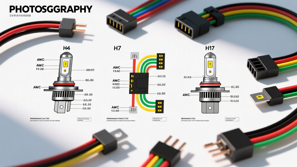
Understanding the Headlight Connector Wiring Diagram
When upgrading vehicle lighting systems—whether transitioning from halogen to LED, installing high-output HID kits, or simply replacing a melted OEM harness—consulting an accurate headlight connector wiring diagram is critical. The headlight circuit operates under high thermal and electrical loads. A mismatched pigtail, incorrect wire gauge, or reversed polarity can result in severe voltage drop, flickering, or catastrophic harness fires. This guide compares the most common automotive headlight connectors, details their specific pinout configurations, and provides a product selection framework for automotive electrical technicians and DIY enthusiasts.
Common Headlight Connector Types & Pinout Configurations
The automotive industry relies on standardized bulb bases, but the wiring harness connectors (pigtails) vary significantly in pin geometry, locking mechanisms, and thermal tolerances. Below is a comparison of the most prevalent headlight connectors found in modern and legacy vehicles.
| Connector Type | Pin Count | Pin 1 Function | Pin 2 Function | Pin 3 Function | Max OEM Wattage | Common Applications |
|---|---|---|---|---|---|---|
| H4 / 9003 / HB2 | 3 | Ground | Low Beam | High Beam | 60W / 55W | Jeep Wrangler, Honda Civic, Toyota Tacoma |
| H7 | 2 | Ground | Low/High Beam | N/A | 55W | BMW 3-Series, VW Golf, Hyundai Sonata |
| H11 / H8 / H9 | 2 | Ground | Low Beam / Fog | N/A | 55W / 35W / 65W | Ford F-150, Chevy Silverado, Nissan Altima |
| 9005 (HB3) / 9006 (HB4) | 2 | Ground | High / Low Beam | N/A | 60W / 51W | GM Trucks, Chrysler/Jeep, Toyota Camry |
H4 / 9003 / HB2 Headlight Connector Wiring Diagram
The H4 (and its US-equivalent 9003/HB2) is a dual-filament bulb requiring a 3-pin connector. Understanding the headlight connector wiring diagram for this setup is vital because the ground circuit carries the combined return current of both filaments if they are momentarily energized together (such as during the high-beam flash-to-pass function).
Pin Assignments and OEM Wire Colors
- Pin 1 (Ground): Typically the center or offset pin depending on the exact housing keyway. OEM wire color is usually Black or White/Black. This wire must be routed to a clean, bare-metal chassis ground or returned directly to the ECU/BCM ground bus.
- Pin 2 (Low Beam): Energized during standard night driving. OEM wire colors vary wildly by manufacturer. For example, GM often uses Tan or Dark Green, while Honda uses Red/White.
- Pin 3 (High Beam): Energized for distance illumination. GM typically uses Dark Green or Light Green, while Ford often uses White/Green.
Expert Insight: When replacing an H4 pigtail, always use a digital multimeter (DMM) to verify the ground pin. Relying solely on aftermarket wire color codes (which often default to Black=Ground, Red=Low, Blue=High) can lead to short circuits if the OEM harness uses a switched-ground system managed by a Body Control Module (BCM).
H11, H7, and 9006 Single-Filament Wiring Diagrams
Single-filament connectors feature two pins. While they appear simple, they present unique challenges, particularly regarding polarity sensitivity when upgrading to LED headlight bulbs.
The Polarity Problem in LED Upgrades
Halogen bulbs are resistive loads; they do not care about current direction. However, LED drivers require specific DC polarity. In many Japanese and European vehicles, the headlight connector wiring diagram reveals a switched ground or reversed polarity layout. For instance, on certain Nissan and Subaru models, the H11 connector Pin 1 is +12V and Pin 2 is Ground, which is the exact opposite of the standard SAE convention. If your LED headlight features a non-polarity-sensing driver, the bulb will not illuminate. Selecting a pigtail with an integrated polarity-reversal adapter or manually swapping the Metri-Pack terminals inside the connector housing is required.
Wire Gauge (AWG) Selection & Voltage Drop Calculations
Selecting the correct wire gauge for your replacement pigtail is non-negotiable. According to SAE International Standard J1128 for low-tension primary cables, automotive wire must handle specific thermal loads without exceeding a 0.5V voltage drop across the circuit.
Current Draw and AWG Sizing Chart
| Bulb Type | Wattage | Current Draw (@ 13.5V) | Recommended AWG (Up to 6ft run) | Recommended AWG (Over 6ft run / Relays) |
|---|---|---|---|---|
| H11 / H8 Halogen | 35W - 55W | 2.5A - 4.1A | 16 AWG | 14 AWG |
| H7 / H4 Low Beam | 55W | 4.1A | 14 AWG | 12 AWG |
| 9005 (HB3) High Beam | 60W - 65W | 4.4A - 4.8A | 14 AWG | 12 AWG |
| Off-Road 100W Halogen | 100W | 7.4A | 12 AWG | 10 AWG |
Warning: Never install 100W halogen bulbs into a factory H4 or H7 wiring harness. The OEM harness is typically 16 AWG or 18 AWG, designed strictly for 55W loads. Upgrading to 100W without installing a dedicated relay harness will melt the connector housing and potentially ignite the harness insulation. For high-wattage setups, refer to Haynes automotive electrical tutorials on integrating 30A/40A Bosch-style relays directly at the battery.
Product Comparison: OEM Plastic vs. Ceramic Pigtails
When browsing for replacement pigtails, you will encounter two primary housing materials: Nylon/Plastic and Ceramic. Understanding the thermal dynamics of the headlight connector wiring diagram environment will dictate your purchase.
Standard Nylon/Plastic Connectors
- Material: Glass-filled Nylon 66 (PA66).
- Thermal Rating: Up to 105°C (221°F).
- Best For: Standard 55W halogen replacements, LED upgrades (which generate minimal forward heat), and sealed cabin-side connections.
- Failure Mode: Over time, engine bay UV exposure and heat cycling cause the locking tabs to become brittle and snap, leading to a loose connection, micro-arcing, and eventual melting.
High-Temp Ceramic Connectors
- Material: Steatite or Alumina Ceramic.
- Thermal Rating: Up to 250°C+ (482°F+).
- Best For: H4/9003 applications, fog lights mounted low in the bumper (high ambient heat), and any setup utilizing 80W+ bulbs.
- Failure Mode: Ceramic does not melt, but the internal metal terminals can still oxidize if not packed with dielectric grease. Furthermore, ceramic is brittle and can shatter if struck by road debris or mishandled during installation.
For a comprehensive breakdown of connector housing materials and terminal retention forces, review the engineering specifications provided by Aptiv (formerly Delphi Automotive).
Proper Splicing and Terminal Crimping Techniques
The most common point of failure in a repaired headlight harness is not the connector itself, but the splice joint where the new pigtail meets the OEM harness. Twisting wires together and wrapping them in electrical tape is an unacceptable practice that violates basic automotive electrical standards.
Step-by-Step Harness Integration
- Cut and Strip: Cut the damaged OEM connector off, leaving enough wire to work with. Strip exactly 5/16' (8mm) of insulation using a precision wire stripper to avoid nicking the copper strands.
- Apply Heat Shrink: Slide a piece of marine-grade, adhesive-lined dual-wall heat shrink tubing over the wire before crimping.
- Crimp: Use a closed-barrel crimp connector or a dedicated Metri-Pack terminal crimp tool. A proper crimp deforms the wire and terminal into a single cold-welded mass. The pull-test strength for a 14 AWG crimp should exceed 45 lbs.
- Seal: Slide the adhesive-lined heat shrink over the crimp and apply heat until the internal sealant oozes out both ends. This prevents capillary action from drawing moisture into the copper strands, which causes green corrosion (copper oxide) and increases circuit resistance.
- Loom and Tape: Wrap the repaired section in TESA cloth automotive harness tape (not vinyl electrical tape, which unrolls in engine bay heat) and secure it inside a split-loom or braided sleeving.
Troubleshooting Common Headlight Wiring Faults
Even with a correct headlight connector wiring diagram, real-world variables can introduce faults. Use this diagnostic matrix to isolate issues:
| Symptom | Probable Cause | Diagnostic Action & Fix |
|---|---|---|
| Headlight flickers at idle but stabilizes when revving | Voltage drop due to undersized ground wire or corroded chassis ground point. | Measure voltage drop across the ground circuit (should be < 0.1V). Clean chassis ground to bare metal and apply dielectric grease. |
| Low beam works, high beam blows the fuse instantly | Melted H4/9003 connector causing Pin 2 and Pin 3 to short together inside the housing. | Inspect connector cavity for carbon tracking or melted plastic. Replace with a ceramic pigtail. |
| LED bulb does not turn on, but halogen worked fine | Reversed polarity in the H11/H7 harness or BCM PWM (Pulse Width Modulation) signaling. | Swap terminal positions in the connector housing. If PWM is present, install an anti-flicker CANbus decoder capacitor inline. |
Final Selection Recommendations
When sourcing your next headlight connector pigtail, prioritize terminal metallurgy and housing integrity. Look for pigtails featuring tinned copper terminals (to resist oxidation) and positive-locking terminal retention systems (TPA - Terminal Position Assurance). Always cross-reference your vehicle's specific factory service manual wiring schematic before cutting into the OEM harness, as aftermarket wire colors rarely match OEM standards. By combining the correct AWG wire, high-temp materials, and proper crimping techniques, you ensure a reliable, safe, and DOT-compliant lighting system.