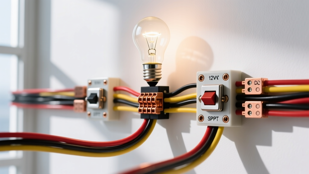
The 12V DC "3-Way" Switch Concept for Vehicles
When planning a custom van build, RV renovation, or sleeper cab upgrade, controlling a single light fixture from two separate locations is a common requirement. Searching for a wiring diagram 1 light 2 switches setup often leads beginners to residential AC electrical guides. However, applying standard household 3-way switch logic to a 12V DC negative-ground automotive system is a critical mistake. Household 3-way switches are designed for alternating current and lack the internal arc suppression required for DC inductive loads, which can lead to melted contacts or electrical fires.
In the automotive and marine sectors, the correct approach to a 1 light 2 switches configuration utilizes two SPDT (Single Pole, Double Throw) switches. This setup is widely used for controlling LED cargo lights in long-wheelbase Sprinter vans, interior hallway lighting in Class A motorhomes, or auxiliary bed lights in custom trucks. This guide breaks down the exact SPDT pinouts, traveler wire routing, and SAE-compliant wire gauge specifications you need to execute this circuit safely and reliably.
Understanding SPDT Switches in Automotive DC Circuits
An SPDT switch, commonly referred to as an "On-On" toggle or rocker switch, features three terminals. The internal wiper connects the center terminal to one of the two outer terminals depending on the toggle position. By linking the outer terminals of two SPDT switches together using "traveler" wires, you create a logic gate that allows either switch to complete or break the circuit to the light fixture.
According to Cole Hersee technical documentation, using heavy-duty automotive-rated SPDT switches ensures the contacts can handle the initial inrush current of halogen or incandescent bulbs, as well as the capacitive inrush of certain LED drivers, without pitting the brass contacts over time.
SPDT Switch Terminal Pinout Guide
| Terminal Label | Alternative Names | Function in DC Circuit |
|---|---|---|
| COM | Common, Center, C | The input or output pivot point. Connects to either L1 or L2. |
| L1 | Normally Open, A, 1 | First traveler terminal. Carries current in one toggle position. |
| L2 | Normally Closed, B, 2 | Second traveler terminal. Carries current in the alternate toggle position. |
Step-by-Step: Wiring Diagram 1 Light 2 Switches
To wire this circuit correctly in a 12V DC environment, you will need two SPDT automotive switches, 14 AWG primary wire, a fuse holder, and a reliable chassis ground point. Always disconnect the negative battery terminal before beginning any automotive electrical work.
Step 1: Power Source to Switch A
Run a fused 12V+ constant or ignition-switched wire from your vehicle's fuse panel or auxiliary busbar to the COM (Common) terminal of Switch A. For a standard interior dome light drawing under 5 amps, a 10A ATO blade fuse is appropriate. Use a ratcheting crimper to attach a fully insulated female spade connector or a heat-shrink ring terminal, depending on your switch type.
Step 2: Routing the Traveler Wires
The traveler wires are the bridge between your two switches. Run two separate wires from Switch A to Switch B. Connect L1 on Switch A to L1 on Switch B, and L2 on Switch A to L2 on Switch B. In automotive wiring, it is best practice to use distinct colors for these travelers to aid in future troubleshooting. Yellow and Green are standard SAE colors for secondary signaling and traveler circuits.
Step 3: Switch B to the Light Fixture
The COM (Common) terminal on Switch B acts as your switched 12V+ output. Run a wire from Switch B's COM terminal directly to the positive input of your light fixture. This wire will only carry voltage when the toggle positions of Switch A and Switch B align to complete the circuit through either the L1 or L2 traveler path.
Step 4: Grounding the Fixture
Connect the negative wire of the light fixture to a clean, bare-metal chassis ground point. Use a self-tapping grounding screw with a star washer to bite through the paint and ensure a zero-resistance path back to the battery negative terminal. Never daisy-chain grounds or rely on aluminum body panels without specialized grounding studs.
Wire Gauge (AWG) and Color Code Standards
Selecting the correct wire gauge is critical, especially in long-wheelbase vehicles where the traveler wires between Switch A (e.g., the cab) and Switch B (e.g., the rear doors) can exceed 20 feet. The SAE J1128 standard dictates the thermal and physical requirements for low-tension primary cable used in automotive applications. Cross-linked polyethylene (XLPE) insulated wire is highly recommended for its resistance to heat, oil, and abrasion.
| Wire Gauge (AWG) | Max Current (Amps) | Recommended Application | Standard SAE Color |
|---|---|---|---|
| 18 AWG | Up to 6A | Low-draw LED puddle lights, indicator lamps | White / Black |
| 16 AWG | Up to 10A | Standard LED interior dome lights, map lights | Red (Power) |
| 14 AWG | Up to 15A | Halogen cargo lights, multiple LED pods | Yellow / Green (Travelers) |
| 12 AWG | Up to 20A | High-power auxiliary work lights (if switched directly) | Blue (Switched Load) |
Note: If your traveler wire run exceeds 15 feet, step up one AWG size (e.g., use 14 AWG instead of 16 AWG) to mitigate voltage drop, which can cause LED drivers to flicker or fail to turn on.
Real-World Troubleshooting & Voltage Drop
Even with a perfect wiring diagram 1 light 2 switches schematic, real-world vehicle environments introduce variables like vibration, corrosion, and voltage drop. Here is how to diagnose common issues using a digital multimeter (DMM).
Symptom: Light Works from Switch A, but Not Switch B
Cause: A broken traveler wire or a loose crimp on the L1/L2 terminals of Switch B.
Fix: Set your multimeter to the continuity (beep) setting. With the battery disconnected, test continuity between Switch A's L1 and Switch B's L1. If the circuit is open, you have a broken wire inside the insulation or a failed crimp. Cut back the wire, strip it with precision wire strippers, and apply a new heat-shrink butt connector.
Symptom: LEDs Flicker or Glow Dimly When Off
Cause: Capacitive coupling or induced voltage from running the 12V+ traveler wires parallel to high-current AC inverter cables or alternator charging lines.
Fix: Reroute the low-voltage DC traveler wires at least 6 inches away from high-current or AC wiring. If rerouting is impossible in a tight van cavity, install a 10k-ohm, 1/2-watt bleeder resistor in parallel across the light fixture's positive and negative terminals to drain phantom voltage.
Calculating Voltage Drop on Long Traveler Runs
In a 40-foot RV or extended Ford Transit, the round-trip wire length from the fuse box, through both switches, to the light and back to ground can easily exceed 60 feet. Use the standard DC voltage drop formula: VD = (2 x L x I x R) / 1000 (where L is one-way length, I is current, and R is wire resistance per 1000ft). For automotive 12V systems, a voltage drop greater than 0.36V (3% of 12V) is unacceptable and will severely shorten the lifespan of sensitive LED drivers. Resources like Del City Wire's technical library offer excellent charts for calculating exact resistance per AWG over distance.
Expert Tips for Reliable 12V Connections
Automotive electrical systems are subjected to constant harmonic vibration and extreme temperature fluctuations. Soldering alone is strictly prohibited in vehicle wiring because solder wicks into the wire strands, creating a rigid point that will inevitably snap under chassis vibration. Always use a ratcheting crimper to secure non-insulated or heat-shrink terminals, ensuring the copper strands are cold-welded inside the barrel. Finally, protect all SPDT switch terminals with dielectric grease to prevent galvanic corrosion, especially in marine or high-humidity RV environments.