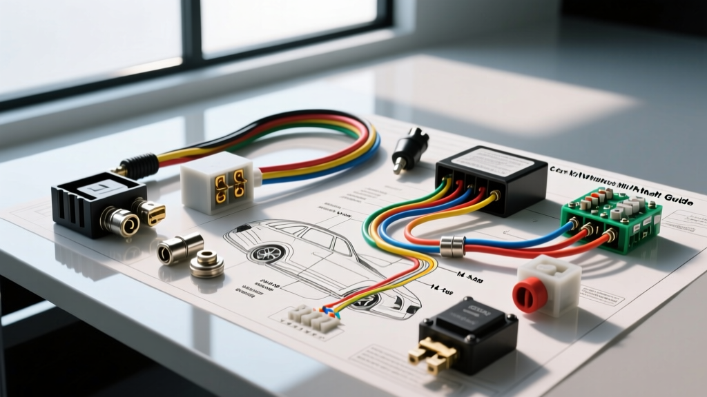
Introduction to Hardwired Anti-Theft Kill Switches
While modern vehicles feature sophisticated factory immobilizers, transponder keys, and encrypted CAN bus networks, professional thieves can bypass these systems using relay amplification attacks or OBD2 key programming tools. A physical, hardwired car kill switch wiring diagram provides an analog fail-safe that cannot be hacked via software or wireless signal spoofing. By physically interrupting a critical powertrain circuit, you render the vehicle completely immobile regardless of the digital security status. This comprehensive walkthrough details the engineering, wire specifications, and exact routing required to install a concealed fuel pump kill switch safely and effectively.
Choosing the Interruption Point: Starter vs. Fuel Pump vs. ECU
When designing an anti-theft immobilizer circuit, selecting the correct wire to interrupt is critical for both security and vehicle health. You generally have three primary options:
- Starter Solenoid Interrupt: Prevents the engine from cranking. While effective, a no-crank condition immediately signals to a thief that an aftermarket immobilizer or starter kill switch is installed, prompting them to search the cabin or steering column for the hidden toggle.
- ECU/PCM Main Power Interrupt: Kills power to the engine control module. This is highly effective but can cause voltage spikes or corrupt ECU memory if the switch is toggled while the engine is running or if the contacts bounce during engagement.
- Fuel Pump Circuit Interrupt: The industry standard for concealed kill switches. The engine will crank normally, but will not start. A thief will typically assume the vehicle has a faulty fuel pump, bad crank sensor, or is out of fuel, rather than suspecting an anti-theft device. This buys you time and deters casual theft attempts.
Core Components and AWG Wire Specifications
Automotive electrical systems demand specific wire insulation and gauge ratings to withstand under-hood temperatures, vibration, and chemical exposure. According to SAE J1128 standards for Low Tension Primary Cable, you must use cross-linked polyethylene (XLPE) insulated wire, such as GXL or TXL, rather than standard PVC wire which becomes brittle and melts near exhaust manifolds.
| Component | Specification | Wire Gauge (AWG) | Connector Type |
|---|---|---|---|
| Fuel Pump Power Feed | GXL Cross-Link, 125°C | 12 AWG | Adhesive Heat-Shrink Butt |
| Relay Coil Trigger | GXL Cross-Link, 125°C | 18 AWG | Sealed Spade / Deutsch DT |
| Hidden Cabin Switch | Marine-Grade SPST Toggle | 18 AWG | Solder & Heat Shrink |
| Secondary Kill Relay | ISO Mini Relay (Bosch Style) | N/A | Weather-Pack 4-Way Pigtail |
| Inline Circuit Protection | MAXI Fuse (20A or 30A) | N/A | Inline Waterproof Holder |
The Secondary Relay Fuel Pump Wiring Diagram Walkthrough
Running heavy 12 AWG fuel pump wires through the vehicle firewall into the cabin is a severe fire hazard and creates a pathway for water intrusion. The correct engineering approach is to use a 'Relay-in-Relay' configuration. The hidden cabin switch only carries the low-amperage trigger current (under 200mA) for a secondary relay located in the engine bay, which then handles the heavy 12V/10A load of the fuel pump.
Step 1: Locating and Tapping the OEM Fuel Pump Relay
Locate the OEM fuel pump relay in the under-hood fuse box. Identify the output wire leaving Pin 87 (Normally Open contact) heading toward the fuel pump. In most domestic V8 applications, this is a Gray or Dark Green wire, while imports often use Yellow/Black or Green/White. Using a digital multimeter, verify this wire shows 12V only during the prime cycle (key-on, engine-off) and while cranking.
Step 2: Installing the Secondary Kill Relay
Mount a secondary ISO mini relay in a protected, dry area of the engine bay. Wire the secondary relay as follows:
- Pin 30 (Common Input): Connect to the OEM harness side of the cut Pin 87 wire. Use a 12 AWG adhesive-lined heat shrink butt connector. For detailed diagnostic baselines of OEM fuel circuits, refer to the AA1Car Fuel Pump Circuit Diagnostics guide.
- Pin 87 (Normally Open Output): Connect to the fuel pump side of the cut Pin 87 wire (12 AWG).
- Pin 85 (Coil Ground): Connect directly to a clean, bare-metal chassis ground using a 14 AWG ring terminal and a self-tapping grounding screw. Apply dielectric grease to prevent corrosion.
- Pin 86 (Coil Power Trigger): This is your control wire. Run an 18 AWG wire from Pin 86 through the firewall grommet into the cabin.
Step 3: Routing the Hidden Cabin Switch
Inside the cabin, route the 18 AWG trigger wire to your chosen hidden location. Connect one side of your concealed SPST (Single Pole Single Throw) switch to the Pin 86 trigger wire. Connect the other side of the switch to a 12V Ignition-Switched source (e.g., the radio or accessory fuse tap). When the hidden switch is ON, it passes 12V to the secondary relay coil, closing Pins 30 and 87, allowing the fuel pump to run. When OFF, the circuit is broken, and the vehicle will crank but never start.
Advanced Hidden Switch Configurations
To maximize security, avoid standard toggle switches that can be spotted by looking under the dash. Consider these advanced configurations:
- Magnetic Reed Switch: A glass-encapsulated reed switch is taped behind a plastic dashboard trim panel or inside the glovebox. It is activated by swiping a small neodymium magnet (disguised as a keychain or pen) over the specific spot on the dash. This leaves zero visible footprint.
- Push-Button Latching Relay: Uses a momentary push-button switch hidden in a dummy OEM switch blank. Pressing the button toggles a solid-state latching relay, requiring no continuous physical 'on' position that a thief could flip.
- Clutch/Brake Pedal Interlock: The kill switch is wired in series with the clutch safety switch (manual) or brake-shift interlock (automatic). The car will only start if the hidden switch is armed AND the pedal is depressed.
Troubleshooting Common Kill Switch Failures
If your vehicle fails to start or the fuel pump whines loudly before failing, the kill switch circuit may be introducing excessive resistance. Follow this diagnostic decision tree:
1. Voltage Drop Testing the Interrupted Circuit
A healthy fuel pump circuit should exhibit minimal voltage drop. Set your multimeter to DC Volts. Place the red probe on the battery positive terminal and the black probe on the fuel pump positive pin (at the tank connector) with the engine running. A reading above 0.5V indicates high resistance. If the voltage drop is concentrated across your secondary kill relay or the hidden switch, the contacts are degraded or the crimps are loose. According to the Littelfuse Automotive Relay Application Guide, relay contact resistance should remain below 50 milliohms throughout its lifecycle.
2. Diagnosing Relay Coil Chatter
If you hear a rapid clicking from the engine bay when the key is turned, the secondary relay coil is not receiving stable voltage. This is often caused by running the 18 AWG trigger wire to a circuit that drops voltage during the starter motor draw (e.g., a non-switched accessory circuit). Ensure the hidden switch draws its 12V source from a true Ignition-Run circuit that remains stable during cranking.
3. Checking for Parasitic Draw
If the vehicle battery dies after sitting for a few days, the kill switch wiring may be creating a ground loop or bypassing the OEM sleep modules. Disconnect the negative battery terminal and place an ammeter in series. Wait 20 minutes for the CAN bus modules to enter sleep mode. If the draw exceeds 50mA, verify that the secondary relay coil (Pin 86) is not back-feeding voltage through the hidden switch's indicator LED (if equipped). Always use switches without built-in illumination LEDs, or ensure they are wired to an ignition-switched ground.
Final Safety and Torque Specifications
When terminating heavy 12 AWG wires at the fuel pump relay or fuse block, use a calibrated crimping tool (such as the TE Connectivity CERTI-CRIMP) to ensure a gas-tight connection. If using threaded terminal blocks, torque the M5 screws to exactly 3.5 Nm to prevent stripping the brass threads while ensuring sufficient clamping force to prevent arcing. Always enclose under-hood secondary relays in a sealed IP67-rated relay harness to prevent moisture ingress, which will rapidly corrode the ISO pins and cause an intermittent no-start condition.