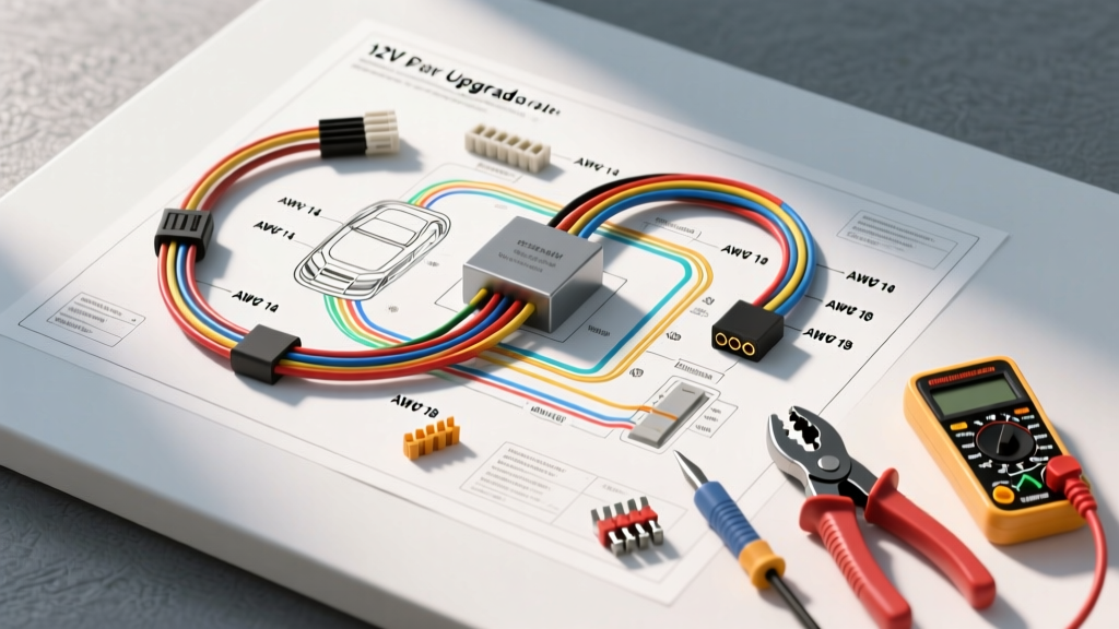
The Anatomy of an Electrical Wiring Diagram Simple Enough for the Garage
When automotive technicians and DIY enthusiasts search for an electrical wiring diagram simple enough to execute in a home garage without factory scan tools or multiplexed CAN-bus decoders, they are almost universally referencing a standard 12V relay-switched circuit. Whether you are installing auxiliary off-road LED light bars on a Jeep Wrangler, adding a winch-in-bed compressor to a Ford F-150, or wiring up aftermarket fog lamps, the foundational schematic remains identical. A basic relay circuit isolates the high-current load from the low-current cabin switch, protecting the vehicle's OEM wiring and body control module (BCM) from thermal overload.
However, interpreting the diagram is only the first step. Executing the build reliably requires a precise understanding of wire gauge ratings, insulation types, crimping mechanics, and terminal selections. In this cost and tool requirements analysis, we break down exactly what you need to build a professional-grade 12V relay harness from scratch, comparing the real-world costs against pre-made aftermarket alternatives.
Mandatory Tooling & Equipment Cost Analysis
Electrical gremlins in aftermarket accessories are rarely caused by the components themselves; they are the direct result of poor terminations and undersized conductors. To build a harness that withstands engine bay temperatures and high-frequency vibration, you must invest in proper tooling. Below is the essential tool matrix required for a professional execution.
| Tool Category | Recommended Specification | Estimated Cost | Purpose |
|---|---|---|---|
| Wire Strippers | Precision AWG gauged (10-22 AWG) | $25 - $45 | Preventing conductor nicking on fine-strand wire |
| Ratcheting Crimper | Hex or Indent die for non-insulated terminals | $40 - $85 | Ensuring gas-tight, cold-weld crimps |
| Heat Gun | Dual temp with reflector nozzle | $30 - $50 | Shrinking adhesive-lined polyolefin tubing |
| Digital Multimeter | True RMS, CAT III rated, continuity beep | $45 - $120 | Testing voltage drop, coil resistance, and shorts |
| Torx/Hex Drivers | Vehicle-specific for ground stud removal | $15 - $30 | Securing ring terminals to chassis grounds |
Why Ratcheting Crimpers are Non-Negotiable
A common failure mode in amateur wiring is the use of cheap, non-ratcheting plier-style crimpers. These tools often deform the terminal barrel unevenly, leaving voids where moisture can ingress, leading to galvanic corrosion and eventual high-resistance failure. A ratcheting crimper (such as those from IWISS or Knoweasy) applies a mathematically precise compression force and will not release until the terminal is fully deformed around the wire strands. This creates a cold-weld bond that is mechanically stronger than the wire itself, a critical requirement for the high-vibration environment of an engine bay.
SAE Wire Standards: Selecting the Right Gauge and Insulation
Not all copper wire is created equal. When sourcing wire for your schematic, you must adhere to SAE J1128 Low Tension Primary Cable Standards. Avoid generic PVC-insulated wire from hardware stores; it becomes brittle at 105°C and will melt if routed near exhaust manifolds.
- GXL (Cross-Linked Polyethylene): Features a thick insulation wall, rated up to 125°C. Ideal for primary battery runs and heavy loads.
- TXL (Thin-Wall Cross-Linked): Offers the same 125°C thermal rating as GXL but with a thinner insulation jacket, making it lighter and more flexible for routing through tight firewall grommets and looms.
For a standard 30A/40A auxiliary light relay circuit, 10 AWG TXL is required for the main power and load paths to minimize voltage drop over long distances (e.g., from the battery to the front bumper). 16 AWG TXL is perfectly adequate for the low-current coil trigger wires running into the cabin.
Decoding the 12V Relay Schematic
The standard Bosch-style Mini ISO 5-pin relay is the backbone of simple automotive electrical diagrams. According to the Littelfuse Mini ISO Automotive Relays Datasheet, these relays utilize a standardized DIN 72552 pin numbering system. Understanding these pinouts is crucial for mapping your diagram to physical wire colors.
| Pin Number | Function | Wire Color (Standard) | AWG Size | Connection Point |
|---|---|---|---|---|
| 30 | Common / Input Power | Red | 10 AWG | Battery Positive (via inline ATC fuse) |
| 87 | Normally Open (NO) Output | Red w/ Blue Stripe | 10 AWG | Load (Auxiliary Lights / Compressor) |
| 85 | Coil Ground | Black | 16 AWG | Chassis Ground or Battery Negative |
| 86 | Coil Power / Trigger | Blue | 16 AWG | Cabin Switch / BCM Trigger Output |
| 87a | Normally Closed (NC) | Unused / Capped | N/A | Not used in standard NO load circuits |
Pins 30 and 87: The High-Current Load Path
Pin 30 receives constant 12V+ from the battery. It is imperative to place an inline ATC or MAXI blade fuse within 18 inches of the battery terminal. If a short occurs between the relay and the battery, the unfused wire can carry enough amperage to ignite the insulation. Pin 87 outputs this 12V+ to the load only when the internal electromagnet pulls the contactor down. Always use Deutsch DT series connectors or sealed Metri-Pack 280 terminals when connecting Pin 87 to exterior accessories to ensure IP67 waterproofing.
Pins 85 and 86: The Low-Current Control Circuit
Pins 85 and 86 activate the internal electromagnetic coil. The coil typically draws between 120mA and 180mA. Because the current is so low, 16 AWG wire is sufficient. Pin 85 is traditionally grounded to the chassis using a ring terminal secured to bare, unpainted metal (always use a star washer to bite through the clear coat and primer). Pin 86 receives the 12V+ trigger signal from your dashboard switch. If you are tapping into an OEM BCM output (like a high-beam pulse), you must use a relay to isolate the BCM, as most factory modules cannot handle the inductive kickback of an aftermarket coil.
Material Cost Breakdown: Scratch-Build vs. Pre-Made Harnesses
Is it cheaper to build your own harness based on a simple diagram, or buy a pre-loomed kit? Let us analyze the economics of a high-quality scratch build versus a premium aftermarket kit (e.g., Hella or Nilight).
| Component | Scratch-Build Cost (High Quality) | Pre-Made Harness Cost |
|---|---|---|
| 10 AWG TXL Wire (15 ft) | $18.00 | Included (Often generic PVC) |
| 16 AWG TXL Wire (10 ft) | $8.50 | Included |
| Bosch/Meyle 40A Relay | $12.00 | $6.00 (Generic brand) |
| Waterproof Relay Socket w/ Pigtails | $9.00 | $4.00 (Non-sealed) |
| Adhesive-Lined Heat Shrink & Terminals | $15.00 | $0 (Usually uses cheap vinyl tape) |
| Inline Fuse Holder & ATC Fuses | $7.00 | $5.00 |
| Total Estimated Cost | $69.50 | $35.00 - $50.00 |
While the scratch-build is roughly 40% more expensive upfront, the use of SAE-rated TXL wire, adhesive-lined heat shrink (which prevents moisture wicking into the copper strands), and a name-brand relay drastically reduces the risk of premature failure, voltage drop, and electrical fires.
Real-World Troubleshooting & Failure Modes
Even with a perfect diagram, physical installation variables can cause system failures. Here is how to diagnose the most common issues using a digital multimeter, referencing the Pico Automotive Relay Testing Guide for advanced oscilloscope and multimeter methodologies.
Diagnosing Voltage Drop Across the Load Path
If your auxiliary lights are dim or flickering, do not immediately blame the lights. Perform a voltage drop test. With the circuit energized, place your multimeter's red probe on the battery positive terminal and the black probe on Pin 30 of the relay. A reading above 0.2V indicates high resistance in the power feed (likely a poor crimp or undersized wire). Next, test from Pin 87 to the positive terminal of the light bar. Excessive voltage drop here means the ground path at the light fixture or the wire run is inadequate.
Coil Resistance and Flyback Diodes
If the relay clicks rapidly or fails to engage, test the coil resistance between Pins 85 and 86. A healthy 12V automotive relay coil should read between 60 and 120 ohms. An infinite reading (OL) indicates an open internal coil winding. Additionally, if your trigger switch utilizes sensitive solid-state electronics or a microcontroller, the inductive voltage spike (flyback) generated when the relay coil de-energizes can damage the switch. In these advanced applications, you must solder a 1N4001 flyback diode across Pins 85 and 86 (stripe facing Pin 86) to safely dissipate the reverse polarity spike.
Conclusion
Mastering a simple electrical wiring diagram is less about memorizing symbols and more about understanding the physical properties of the materials you are manipulating. By investing in ratcheting crimpers, adhering to SAE J1128 wire specifications, and rigorously testing your terminations, you transform a basic schematic into a bulletproof, OEM-quality electrical system capable of surviving the harshest automotive environments.