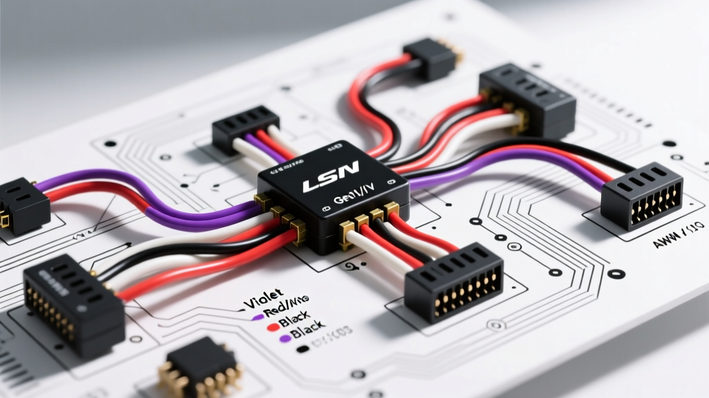
Decoding the LS Engine Wiring Diagram: Beyond the Basics
Executing a flawless Gen III or Gen IV LS swap requires far more than connecting the battery and turning the key. The GM LS platform relies on a highly integrated Powertrain Control Module (PCM) that demands precise voltage references, dedicated grounding topologies, and strict adherence to wire gauge specifications. Whether you are integrating a 5.3L LM7 into a classic chassis or wiring a 6.2L LS3 with an E38 controller, understanding the underlying LS engine wiring diagram is critical to avoiding parasitic draws, sensor correlation codes, and catastrophic injector failures.
This advanced technical deep dive bypasses generic swap guides, focusing instead on OEM PCM cavity pinouts, Hall-effect sensor shielding requirements, and the specific CAN-bus termination protocols required for late-model E38/E40 controllers. For comprehensive factory cavity layouts, technicians frequently cross-reference shbox.com's PCM Pinout archives, which remain the gold standard for Gen III P01/P59 ECM mapping.
Core PCM Architecture: P01/P59 vs. E38/E40
The physical and electrical architecture of the LS PCM dictates your entire harness layout. Early Gen III and Gen IV engines (1997-2007) typically utilize the P01 or P59 PCM. These feature three distinct 40-pin connectors, color-coded as C1 (Black), C2 (Blue), and C3 (Red). In contrast, the Gen IV E38 and E40 PCMs (2008+) utilize a completely different 38-pin and 34-pin cavity layout with integrated CAN-bus networking, requiring a fundamentally different approach to chassis integration.
P59 Connector Cavity Assignments (Gen III/Early Gen IV)
- Connector C1 (Black): Dedicated to main power feeds, ignition relays, and high-current grounds. Pin 20 and Pin 57 are your primary 12V battery feeds, requiring a minimum of 10 AWG wire directly from the distribution block.
- Connector C2 (Blue): Houses the injector drivers and Ignition Control Module (ICM) signals. Injector control wires are typically 18 AWG. The PCM switches the ground side of the injector circuit; therefore, the 12V feed to the injectors must be sourced from a dedicated, fused ignition relay.
- Connector C3 (Red): Contains low-voltage sensor signals, including the MAF, TPS, MAP, and O2 sensors. Signal wires here are highly susceptible to Electromagnetic Interference (EMI) and must be routed away from secondary ignition components.
Critical Sensor Pinouts and Wire Color Codes
Sensor signal integrity is the most common failure point in aftermarket LS harnesses. Using incorrect wire gauges or failing to shield Hall-effect sensor circuits will result in erratic timing pulls and misfires. Below is the OEM specification chart for the most critical engine management sensors on a standard 24x reluctor P59 setup.
| Sensor Type | Function | OEM Wire Colors (Signal/Gnd/12V) | PCM Cavity (P59 C3 Red) | Wire Gauge & Shielding |
|---|---|---|---|---|
| Mass Air Flow (MAF) | Calculates air mass for fueling | Yellow / Black / Pink | Pin 48 (Sig) / 49 (Gnd) / 79 (12V) | 20 AWG Shielded |
| Crank Position (CKP) | 24x Reluctor timing reference | Dark Blue / Black / Pink | Pin 21 (Sig) / 22 (Gnd) / 53 (12V) | 20 AWG Shielded |
| Cam Position (CMP) | 1x Sync for sequential fuel | Dark Green / Black / Pink | Pin 23 (Sig) / 24 (Gnd) / 54 (12V) | 20 AWG Shielded |
| Manifold Pressure (MAP) | Speed-density load calculation | Yellow / Black / Pink | Pin 37 (Sig) / 38 (Gnd) / 36 (5V Ref) | 20 AWG Unshielded |
| Throttle Position (TPS) | Throttle blade angle mapping | Dark Blue / Black / Gray | Pin 33 (Sig) / 16 (Gnd) / 15 (5V Ref) | 20 AWG Unshielded |
Note: For 58x reluctor engines (Gen IV LS2/LS3/L99), the Crank Position Sensor operates on a different voltage threshold and signal frequency. Never mix 24x and 58x sensor harnesses without re-pinning the PCM and flashing the corresponding Operating System (OS).
Power, Ground, and CAN-Bus Routing Specifications
A recurring issue in LS swaps is the reliance on the engine block as a primary ground return path for the PCM. According to SAE J1113 standards for electromagnetic compatibility, relying on cast-iron or aluminum block mating surfaces for high-frequency PCM grounds introduces variable resistance, leading to erratic sensor readings.
The Star Grounding Protocol
All PCM ground wires (typically Black or Black/White, 12 AWG) must be terminated using a "star ground" configuration. This involves crimping all PCM ground wires, injector grounds, and coil grounds into a single, heavy-duty copper ring terminal (preferably 3/8" or M10). This terminal must be bolted directly to a clean, bare-metal surface on the cylinder head or intake manifold, torqued to 15 lb-ft. Do not use star washers, which can bite into the terminal and create micro-arcing points under high thermal expansion.
CAN-Bus Topology for E38/E40 Swaps
When wiring a late-model E38 PCM, the Controller Area Network (CAN) bus becomes mandatory for communication with the TCM (Transmission Control Module) and BCM (Body Control Module).
- CAN High: Typically Green/White or Dark Green.
- CAN Low: Typically Green/Black or Light Green.
- Termination: The CAN-bus requires exactly two 120-ohm terminating resistors located at the extreme ends of the network topology. The E38 PCM contains one internal 120-ohm resistor. If you are running a standalone harness without a TCM, you must wire an external 120-ohm resistor across the CAN High and CAN Low pins at the OBD-II diagnostic port to prevent U0100 (Lost Communication) codes and limp-mode defaults.
Injector and Coil Driver Circuit Topology
The P59 PCM utilizes a "low-side driver" topology for fuel injectors. This means the PCM provides the ground path to fire the injector. The 12V power feed to the injectors must be capable of handling the cumulative amperage of the injector bank. A standard LS 5.3L uses high-impedance injectors (approx. 11-12 ohms), drawing roughly 1 amp per injector. However, during peak-and-hold firing phases, current spikes can exceed 4 amps per injector.
Your main injector power feed wire must be a minimum of 12 AWG, fed through a 30A Bosch-style relay, and split into 18 AWG pigtails for each individual injector. Using undersized wire on the 12V feed will cause voltage drop across the injector bank, resulting in a lean condition at high RPM (often misdiagnosed as a failing fuel pump).
Ignition coils on the LS platform are "Coil-Near-Plug" (CNP). The PCM sends a 5V logic signal to the coil's internal igniter. The coil requires three wires: 12V Ignition (Pink), Ground (Black), and ICM Signal (typically White or Yellow). Ensure the coil ground is dedicated and not shared with high-current accessories like electric fans or fuel pumps.
Real-World Failure Modes and Diagnostic Troubleshooting
Even with a pristine LS engine wiring diagram in hand, environmental factors and minor pinning errors can cause severe drivability issues. Below is a diagnostic decision tree for the most common swap-related electrical faults.
Fault: P0016 (Crankshaft/Camshaft Position Correlation)
- Cause 1 (Electrical): Sensor signal wires routed too close to exhaust headers or secondary spark plug wires, inducing EMI noise that the PCM reads as extra reluctor teeth.
- Fix: Reroute CKP and CMP sensor harnesses. Ensure the shield drain wire on the sensor pigtail is grounded only at the PCM connector cavity, not at the sensor end, to prevent ground loops.
- Cause 2 (Mechanical): Single-bolt cam sprocket gear walk or stretched timing chain altering physical timing.
Fault: P0101 (Mass Air Flow Circuit Range/Performance)
- Cause: Voltage drop on the 12V ignition feed to the MAF sensor. The MAF requires a stable 12V reference. If the wire is tapped into a shared circuit (like the fuel pump relay), voltage fluctuations will skew the MAF frequency output.
- Fix: Run a dedicated 18 AWG 12V ignition feed directly from the main PCM relay block to the MAF Pink wire. Verify voltage at the sensor connector with the engine running; it should not drop below 11.8V.
Fault: Random Misfires at High RPM (No Codes)
- Cause: Injector ground wire undersized or PCM ground star-point oxidized. As RPM increases, the injector pulse width shrinks. Any resistance in the ground circuit delays the PCM's ability to pull the injector driver low, effectively shortening the pulse width and leaning out the cylinder.
- Fix: Perform a voltage drop test across the PCM ground circuit with the engine under load. A drop greater than 0.1V indicates a compromised ground terminal. Sand the cylinder head mounting point to bare metal and apply dielectric grease over the tightened terminal.
Final Integration and Testing
Before applying power to your newly wired LS harness, perform a comprehensive continuity check using a digital multimeter. Verify that no sensor 5V reference wires (Gray) are shorted to ground, as this will instantly destroy the internal voltage regulator inside the P59 or E38 PCM. For further OEM specification validation, always consult the latest crate engine wiring manuals available through Chevrolet Performance Parts to ensure your aftermarket harness matches the exact pinout of your specific engine controller OS.
By adhering to strict wire gauge specifications, utilizing shielded cables for Hall-effect sensors, and implementing a true star-ground topology, your LS swap will yield OEM-level reliability and throttle response, entirely free from the electrical gremlins that plague lesser installations.