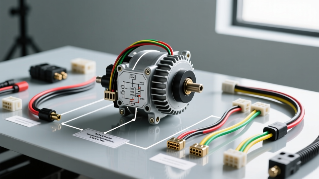
Introduction to the Car Alternator Wiring Schematic
Decoding a car alternator wiring schematic is a fundamental skill for automotive electricians, hot rod builders, and restoration specialists. While modern vehicles utilize complex LIN-bus or CAN-bus controlled alternators managed by the PCM, the vast majority of classic cars, trucks, and aftermarket crate engines rely on the legendary General Motors Delco Remy SI (System Integrated) and CS (Charging System) series alternators. These units serve as the benchmark for understanding automotive charging circuits. In this complete wiring diagram walkthrough, we will dissect the standard 3-wire schematic, explore the 4-pin CS130 evolution, and analyze the controversial 1-wire conversion, providing exact AWG specifications, pinout data, and real-world diagnostic procedures.
Decoding the Standard 3-Wire GM SI-Series Schematic
The GM SI10 and SI12 alternators (commonly found on 1973-1986 GM vehicles and universally adopted in aftermarket applications) utilize a 3-wire configuration. This setup is widely considered the gold standard for voltage regulation accuracy and dash integration. The internal voltage regulator requires three distinct connections to function optimally: the main battery output (BAT), the exciter/lamp circuit (Terminal 1), and the remote voltage sense circuit (Terminal 2).
Terminal Pinout and Wire Color Codes
When wiring an SI-Series alternator, adhering to OEM wire color codes and minimum AWG (American Wire Gauge) requirements is critical to prevent voltage drop and thermal runaway. Below is the definitive specification chart for a standard 3-wire car alternator wiring schematic.
| Terminal | Function | Standard GM Wire Color | Min AWG (High Amp) | Circuit Protection |
|---|---|---|---|---|
| BAT | Main DC Output to Battery | Red | 8 AWG (or 6 AWG for 100A+) | 150A Mega Fuse or Fusible Link |
| 1 (L) | Exciter / Dash Charge Lamp | Brown or Dark Green | 18 AWG | 5A Inline Fuse (Optional) |
| 2 (S) | Remote Voltage Sense | Red or Orange | 14 AWG | 20A Inline Fuse at Battery |
The LED Dash Light Trap: A Common Wiring Failure
A frequent failure mode when updating a classic car's wiring harness is swapping incandescent dash bulbs for LEDs. The SI-Series internal regulator uses Terminal 1 (L) to receive a small initial base current (typically 35-50mA) through the dash bulb to energize the rotor's field coil. An incandescent 194 bulb provides the correct resistance path. An LED bulb, however, has a built-in current-limiting resistor and a diode that often blocks the necessary initial current. If you wire an LED directly to Terminal 1, the alternator will fail to 'excite' at idle, resulting in a dead battery unless you rev the engine to 2,500+ RPM to force self-excitation via residual magnetism. The Fix: Solder a 50-ohm, 5-watt ceramic resistor in parallel with the LED dash bulb to restore the proper excitation circuit path.
The CS130 4-Pin Evolution Schematic
In 1987, GM introduced the CS130 alternator to handle higher electrical loads and integrate with early body control modules. The CS130 utilizes a 4-pin regulator connector, though only three or four wires are used depending on the exact schematic. Understanding this car alternator wiring schematic is vital for LS-engine swaps and late-model restomods.
| Pin | Designation | Function & Wiring Directive |
|---|---|---|
| P | Phase | Connects to the stator winding. Used by the PCM to read alternator RPM. Rarely used in standalone aftermarket harnesses. |
| L | Lamp | Turns on the dash 'GEN' or 'ALT' light. Requires a 50-ohm resistor or incandescent bulb in the circuit. |
| I | Ignition | Switched 12V+ from the ignition switch. Wakes up the regulator. Can be jumpered to the L terminal in simple setups. |
| S | Sense | Must be routed directly to the positive battery post or main distribution block for accurate voltage regulation. |
The 1-Wire Alternator Conversion Schematic
The 1-wire alternator is heavily marketed in the hot rod and street rod community for its 'clean engine bay' aesthetic. In a 1-wire car alternator wiring schematic, the internal regulator is modified (or an external jumper is installed inside the alternator case) to connect the Sense terminal directly to the BAT terminal. Terminal 1 (Exciter) is either eliminated or internally looped.
Pros and Cons of the 1-Wire Setup
- Pros: Requires only a single heavy-gauge wire from the alternator to the battery. Eliminates the dash light and sense wire routing, simplifying custom chassis builds.
- Cons: Because the sense wire is attached directly to the alternator output stud, the regulator only measures voltage at the alternator, not at the battery or the fuse block. If there is a 0.5V drop across the main battery cable and fuse block, the battery will only see 13.7V while the alternator pushes 14.2V. Furthermore, 1-wire units almost always require the driver to 'blip' the throttle upon startup to excite the field coil, as they lack the dash-bulb exciter circuit.
Wire Selection, Routing, and Termination Standards
When executing any car alternator wiring schematic, the physical materials used are just as important as the diagram itself. According to SAE J1128 Wiring Standards, automotive primary wire must withstand high under-hood temperatures and chemical exposure.
- Wire Jacket: Never use standard PVC hardware store wire. You must use TXL, GXL, or SXL (Cross-Linked Polyethylene) wire, which is rated for continuous 125°C to 155°C operation and resists melting against exhaust headers.
- Termination: Do not solder high-amperage alternator connections. Solder is brittle and will crack under the high-frequency vibration of the alternator bracket, leading to arcing and fires. Use Mil-Spec adhesive-lined heat shrink crimp terminals with a calibrated ratcheting crimper.
- Routing: Route the main BAT cable and the Sense wire on opposite sides of the engine bay if possible. Keep the Sense wire away from high-current ignition wires (like MSD 8.5mm Super Conductor) to prevent electromagnetic interference (EMI) from inducing false voltage spikes that trick the regulator.
Real-World Failure Modes & Multimeter Diagnostics
Even with a perfect car alternator wiring schematic on paper, physical degradation causes charging system failures. The most common issue is a high-resistance fault in the Sense (S) wire circuit.
Voltage Drop Testing the Sense Wire
If your vehicle is overcharging (boiling the battery acid, blowing headlight bulbs), the regulator is likely losing its sense ground or positive reference. Perform this definitive voltage drop test:
- Start the engine and turn on high electrical loads (headlights on high beam, HVAC blower on max, rear defroster on).
- Set your digital multimeter to DC Volts.
- Place the Red probe directly on the alternator's main BAT output stud.
- Place the Black probe on the positive battery post (not the clamp, the actual lead post).
- Analysis: A reading above 0.2V indicates excessive resistance in the main charge cable or the sense wire circuit. The regulator is compensating for the voltage drop by overcharging the system. Clean the battery terminals, upgrade to 4 AWG cable, and re-crimp the alternator ring terminal.
Authoritative References
For further study on OEM charging system architectures and circuit protection standards, consult the following resources:
- MAD Electrical Alternator Tech - The definitive guide to GM SI and CS series alternator wiring and dash lamp resistance requirements.
- SAE J1128 Wiring Standards - Society of Automotive Engineers specifications for low-tension primary cable (TXL/GXL/SXL) temperature and abrasion ratings.
- Delco Remy Technical Resources - OEM service manuals and diagnostic flowcharts for heavy-duty and light-duty alternator systems.