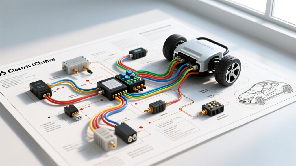
Understanding the DS Electric 48V Architecture
The Club Car DS platform remains one of the most iconic and widely serviced electric golf carts in the world. When transitioning from older 36V setups or maintaining factory 48V models, understanding the specific DS electric 48V Club Car wiring diagram is critical for accurate diagnostics. A 48 volt system typically utilizes six 8V deep-cycle batteries (such as the Trojan T-875) or four 12V batteries wired in series, delivering a fully charged pack voltage of approximately 50.9V to 51.2V. This higher voltage architecture reduces amperage draw for the same horsepower output, minimizing voltage sag and heat generation across the 2 AWG primary harness.
Troubleshooting a 48V DS requires a systematic approach. Unlike simple resistive circuits, the modern 48V DS (often equipped with a Curtis 1268 controller or the proprietary Club Car IQ system) relies on a complex network of logic signals, inductive throttle sensors, and high-amperage contactors. According to SAE International standard J1128 for low-tension primary cable, ensuring the integrity of the high-current paths is the first step in any EV diagnostic flow.
Core Wiring Harness & AWG Specifications
Before executing the troubleshooting flow, verify that the physical wiring matches OEM specifications. Undersized cables or corroded lugs are the leading cause of false controller fault codes and intermittent power loss.
- Main Battery Cables (B+ to Solenoid, Solenoid to Controller): 2 AWG or 1/0 AWG stranded copper. OEM color is typically Red for B+ and Black for B-. Torque battery terminal lugs to 110 in-lbs.
- Controller to Motor (Armature & Field): 2 AWG stranded copper. Motor terminal nuts (3/8-16) must be torqued to 18-20 ft-lbs to prevent arcing and stud melting.
- Logic & Throttle Harness: 16 AWG to 18 AWG. These low-current wires carry 5V references and millivolt signals; they must be routed away from the high-amperage motor cables to prevent electromagnetic interference (EMI).
- Solenoid Coil Circuit: 16 AWG. Typically Blue/White or Yellow, carrying the activation signal from the controller or ignition switch.
Step-by-Step Troubleshooting Flow: No-Start & Power Loss
Use the following decision-tree flow to isolate faults within the 48 volt system. Always use a digital multimeter (DMM) capable of reading DC voltage and resistance accurately.
Step 1: Battery Pack & Main Solenoid Verification
Symptom: Cart is completely dead; no solenoid click when the pedal is pressed.
- Measure Pack Voltage: Place DMM probes on the main B+ and B- battery posts. A healthy 48V pack should read >48.0V. If it reads below 44V, the controller's Low Voltage Cutoff (LVC) is actively preventing operation to protect the batteries from deep discharge. Reference Trojan Battery maintenance guidelines for proper equalization charging procedures.
- Verify Key & FNR Logic: Turn the key to ON and toggle the Forward/Reverse (FNR) switch. Listen for the microswitch clicks. Measure voltage at the solenoid's small activation terminals. You should see full pack voltage (approx. 48V-51V) when the pedal is depressed.
- Solenoid Coil Test: If there is no voltage at the small terminals, the issue is upstream (key switch, FNR switch, or controller logic). If you do have 48V at the small terminals but no click, disconnect the battery and measure the solenoid coil resistance. A standard 48V Albright or Trombetta contactor coil should read between 14 and 18 ohms. An infinite reading indicates an open coil; replace the solenoid.
- Main Contact Voltage Drop: If the solenoid clicks but the cart won't move, measure the voltage drop across the two large solenoid studs while a helper presses the pedal. A voltage drop greater than 0.2V indicates welded, pitted, or carbon-fouled internal contacts.
Step 2: Throttle Input Device Testing (V-Glide vs. MCOR)
Symptom: Solenoid clicks, but the motor does not engage, or the cart surges unpredictably.
Early DS models utilized a V-Glide (resistor coil and microswitches), while later 48V IQ models use an MCOR (inductive/Hall-effect) or a standard 0-5k ohm potentiometer.
- Testing 0-5k Ohm Potentiometer: Back-probe the three throttle wires at the controller. Pin 1 (Yellow) should provide a steady 5V reference. Pin 3 (Black) is ground. Pin 2 (Green/Signal) should read approximately 0.8V at idle and sweep smoothly to 3.5V - 4.2V at full throttle. Any dead spots or sudden voltage spikes indicate a worn carbon track. Replace the throttle assembly.
- Testing the MCOR (Inductive): The MCOR does not use physical contacts. Verify the 5V supply and ground. The signal wire will output a varying frequency or specific analog voltage curve depending on the exact IQ controller generation. If the cart throws a "Throttle Fault" code (e.g., Blink Code 4 or 5 on the IQ dash), check for moisture ingress in the MCOR housing, which is a notorious failure point.
Step 3: Controller Logic & High Pedal Disable (HPD)
Symptom: Cart only moves if you turn the key on after releasing the pedal, or it refuses to move entirely despite a good solenoid click.
The 48V Curtis and IQ controllers feature High Pedal Disable (HPD) and Rollback Protection. If the controller detects a throttle signal >0.8V upon initial key-up, it locks out the motor output to prevent accidental lurching.
- Turn the key OFF.
- Depress the pedal fully.
- Turn the key ON. The cart should not move, and the solenoid may not engage. This confirms HPD is functioning.
- Release the pedal, wait two seconds, and press again. The cart should now operate. If it does not, check the throttle return spring and the idle microswitch alignment. The microswitch must open the circuit completely when the pedal is at rest.
48V Controller Pinout & Logic Signal Reference
The following table outlines the standard pinout for the widely used Curtis 1268 (and compatible IQ) 48V controllers found in the DS platform. Always verify against the specific wiring decal located inside your controller access panel, as OEM harness adapters can alter physical plug positions.
| Pin | Function | Wire Color (Typical) | AWG | Voltage / Signal Spec |
|---|---|---|---|---|
| 1 | B+ (Main Positive) | Red | 2 | 48V - 51.2V DC |
| 2 | M- (Motor Negative) | Black | 2 | Switched Ground / PWM |
| 5 | Solenoid Coil Output | Blue/White | 16 | 48V DC (When active) |
| 11 | Forward Input | Green/White | 16 | B+ Voltage (FNR Fwd) |
| 12 | Reverse Input | Blue/White | 16 | B+ Voltage (FNR Rev) |
| 16 | Throttle 5V Reference | Yellow | 18 | 5.0V DC (+/- 0.1V) |
| 17 | Throttle Signal (Wiper) | Green | 18 | 0.8V (Idle) to 4.2V (WOT) |
| 18 | Throttle Ground | Black | 18 | 0V (Logic Ground) |
For deeper controller programming and fault-code interpretation, technicians should consult the official Curtis Instruments vehicle controller documentation or use the Curtis 1313 handheld programmer to read live logic states.
Advanced Diagnostics: Pre-Charge Circuits & Motor Testing
A critical but often overlooked component in the DS electric 48V Club Car wiring diagram is the pre-charge circuit. When the main solenoid engages, the controller's internal capacitors act like a dead short for a fraction of a second. Without a pre-charge resistor (typically a 470-ohm, 5W ceramic resistor wired across the large solenoid terminals), the massive inrush current can weld the solenoid contacts or blow the controller's internal diodes.
- Testing the Pre-Charge Resistor: Disconnect the battery. Set your DMM to Ohms. Measure across the resistor. It should read approximately 470 ohms. If it reads infinite, replace it immediately before running the cart, or you risk catastrophic contactor failure.
- SepEx Motor Testing: The 48V DS uses a Separately Excited (SepEx) ADC motor. This motor has four terminals: A1, A2 (Armature) and F1, F2 (Field). The Armature circuit handles the heavy current (2 AWG), while the Field circuit allows the controller to manipulate the magnetic field for regenerative braking and speed control. Measure resistance between A1 and A2; it should be extremely low (typically < 0.5 ohms). Measure between F1 and F2; it should read slightly higher (approx. 1.0 to 2.5 ohms). If you measure continuity between any Armature terminal and the motor case (Ground), the motor has a shorted winding and must be rebuilt or replaced.
Safety Protocols & Final Verification
Working on a 48 volt system presents significant arc-flash and electrocution hazards. Always disconnect the main negative battery cable first, and reconnect it last. When tightening 2 AWG lugs on the controller and solenoid, ensure no stray wire strands are bridging the gap between the B+ terminal and the aluminum controller chassis, as this will instantly destroy the controller's logic board. By following this structured troubleshooting flow and referencing the precise wire colors and pinouts detailed above, you can accurately isolate and repair faults within the DS 48V electrical architecture, ensuring reliable performance and maximizing battery lifespan.