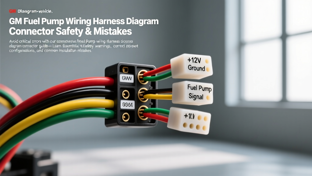
Critical Safety Protocols for GM Fuel System Electrical Work
Working on the fuel delivery system of General Motors trucks and SUVs (Silverado, Sierra, Tahoe, Suburban) requires strict adherence to electrical and chemical safety. The transition point between the chassis harness and the in-tank fuel module is a notorious failure point. When referencing a GM fuel pump wiring harness diagram, the connector specifications and pinout tolerances dictate the longevity of the repair. Ignoring the SAE J1128 standards for automotive primary cable and connector sealing leads to catastrophic melting, voltage starvation, and potential fuel vapor ignition.
The GM Fuel Pump Wiring Harness Diagram Connector Layout
Most GM GMT800 and GMT900 platforms utilize a 4-way or 5-way Delphi Metri-Pack 280 series weather-pack connector at the top of the fuel tank. Below is the definitive pinout and wire specification chart based on OEM service data and GM Upfitter electrical schematics.
| Pin | Circuit Function | OEM Wire Color | Wire Gauge (AWG) | Terminal Type |
|---|---|---|---|---|
| A | Fuel Pump Feed (12V+) | Gray | 14 AWG (GXL) | Metri-Pack 280 Female |
| B | Fuel Pump Ground | Black | 14 AWG (GXL) | Metri-Pack 280 Female |
| C | Fuel Level Sender Signal | Purple | 20 AWG | Metri-Pack 150 Female |
| D | Sender Ground / EVAP Return | Pink w/ White Tracer | 20 AWG | Metri-Pack 150 Female |
5 Fatal Mistakes When Splicing GM Fuel Pump Connectors
Mistake 1: Ignoring the High-Current Ground Path Voltage Drop
The most common reason a newly replaced GM fuel pump burns out prematurely is a poor ground. The factory black 14 AWG ground wire routes to a chassis ground point (often G103 or G400 depending on the model year). Over time, these frame grounds corrode. If you splice a new ACDelco PT88 pigtail connector into the harness without performing a voltage drop test on the ground circuit, the pump will pull excess amperage to compensate for the resistance. A healthy ground circuit should exhibit less than 0.2V drop under load. Always run a dedicated 12 AWG ground wire directly to the battery negative or a verified clean chassis point if the factory ground exceeds 0.5 ohms.
Mistake 2: Using Unsealed Vinyl Butt Connectors
The area above the fuel tank is a harsh environment exposed to road salt, water, and highly corrosive fuel vapors. Standard vinyl butt splices are completely inadequate for a GM fuel pump wiring harness diagram connector repair. Fuel vapors will permeate the vinyl insulation, causing the copper strands to oxidize and turn black, leading to high resistance and melted connector pins. You must use adhesive-lined polyolefin heat shrink terminals or, preferably, a factory-style sealed pigtail with Delphi weather-pack seals. The heat shrink must contain an inner layer of hot-melt adhesive that seals the wire insulation to the barrel, preventing vapor intrusion.
Mistake 3: Overloading Factory 14 AWG Wiring with High-Flow Pumps
Enthusiasts frequently upgrade to high-flow in-tank pumps (like the Walbro 450 / 340 LPH) for boosted applications. The factory GM wiring harness uses 14 AWG wire rated for roughly 15-18 amps in a bundled harness configuration. A high-flow pump can spike to 22+ amps on startup. Pushing this current through the factory gray 14 AWG feed wire and the standard fuel pump relay in the underhood fuse block will melt Pin A on the tank connector. If your diagram shows a high-draw pump, you must install a heavy-duty fuel pump relay bypass kit.
Mistake 4: Misinterpreting the Fuel Level Sender Circuit
The fuel level sender operates on a 0-90 ohm or 0-288 ohm resistance sweep (depending on the exact year and PCM calibration). The signal wire (Purple, Pin C) is extremely sensitive to added resistance. A common mistake is using a standard wire tap or twisting the 20 AWG sender wire with a thicker 16 AWG wire. This introduces parasitic resistance, causing the fuel gauge to read inaccurately or trigger a P0463 (Fuel Level Sensor High Circuit) code. Always use 20 AWG wire for sender splices and solder the connection.
Mistake 5: Failing to Lock the Connector TPA (Terminal Position Assurance)
Delphi Metri-Pack connectors utilize a secondary red or yellow plastic lock (TPA) that snaps into place after the terminals are inserted. Many technicians push the new pigtail terminals into the housing but forget to install the TPA lock. Under the constant vibration of a truck chassis, the terminals will back out slightly, causing an intermittent open circuit or an electrical arc inside the connector housing, which quickly melts the plastic shell.
Safety Warnings: Preventing Fuel Vapor Ignition
Before cutting, splicing, or testing any part of the fuel pump wiring harness, you must mitigate the risk of vapor explosion. The National Fire Protection Association (NFPA) and OSHA guidelines for automotive repair dictate strict protocols when working near open fuel systems.
- Disconnect the Battery: Always remove the negative battery terminal before dropping the tank or lifting the truck bed. A stray spark from a multimeter probe or a shorted wire can ignite pooled fuel.
- Relieve Fuel Pressure: GM systems operate at 55-65 PSI. Pull the fuel pump relay in the underhood fuse block, crank the engine until it stalls, and then disconnect the battery. Alternatively, use a fuel pressure gauge on the Schrader valve to safely bleed the rail into a catch can.
- Ventilate the Work Area: Fuel vapors are heavier than air and will pool in the bed of a truck or under a lift. Use explosion-proof fans to move air across the workspace.
- Avoid Bed Lifting Hazards: Many technicians lift the truck bed to access the harness connector rather than dropping the rusted tank straps. If you lift the bed, use heavy-duty wooden blocks or dedicated bed lift stands. Never rely solely on a hydraulic floor jack to support the bed while you are working underneath the harness.
The Relay Bypass Solution for High-Current Applications
If your GM fuel pump wiring harness diagram connector shows signs of thermal damage (melted plastic around Pin A), or if you are installing a pump drawing over 15 amps, a relay bypass is mandatory. This preserves the factory PCM control while providing a dedicated high-current path.
- Trigger Wire: Tap into the factory Gray 14 AWG fuel pump feed wire near the underhood fuse block. This wire will now only carry the low-amperage trigger signal for the new relay coil (Pin 85).
- Relay Ground: Connect Pin 86 of a Bosch-style 30A relay to a clean chassis ground.
- High Current Feed: Run a new 10 AWG wire from the battery positive (with an inline 30A MAXI fuse) to Pin 30 of the relay.
- Pump Feed: Run a new 12 AWG GXL wire from Pin 87 of the relay directly to the Gray wire at the tank connector, bypassing the entire length of the factory chassis harness.
This configuration ensures the Metri-Pack 280 connector at the tank receives a full 14.0V+ under load, eliminating the voltage drop that causes premature pump failure and connector melting. For comprehensive wiring standards, refer to Delphi Technologies connector specifications and ensure all crimps meet OEM pull-test requirements.