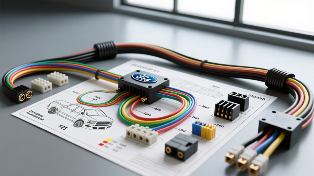
Demystifying the Ford F250 Upfitter Switch Wiring Diagram
If you own a Ford F-250 Super Duty, the factory-installed upfitter switches are one of the most valuable tools for customizing your truck. Whether you are wiring a winch control, LED light bars, a snow plow, or an onboard air compressor, understanding the Ford F250 upfitter switch wiring diagram is essential. For beginners, automotive wiring can seem intimidating, but Ford’s upfitter system is specifically designed to take the guesswork out of adding high-draw accessories.
Unlike older vehicles where you had to tap into the fuse box, run new power lines from the battery, and install aftermarket relay harnesses, the F-250’s upfitter system is pre-wired from the factory. The heavy-gauge wires are already routed through the firewall, protected by fuses, and controlled by heavy-duty relays. Your only job is to locate the blunt-cut wires under the dash and connect them to your accessory. This guide will break down the circuit logic, wire color codes, amperage limits, and step-by-step installation procedures to ensure your first wiring project is a success.
How the Factory Upfitter Circuit Actually Works
Before cutting or stripping any wires, it is crucial to understand the anatomy of the upfitter circuit. A common beginner mistake is adding an unnecessary aftermarket relay to a circuit that already has one. Here is how the factory system operates:
- The Dash Switch: When you flip the toggle switch on your dashboard, it sends a low-current signal to the Body Control Module (BCM) or directly to the relay coil.
- The Relay Coil: This signal energizes the electromagnet inside the factory relay, which is located in the Power Distribution Box (PDB) under the hood.
- The Load Circuit: The energized relay closes a high-current contact, allowing 12V power from the battery (protected by a high-amperage fuse) to flow down the blunt-cut wire located under the driver’s side dashboard.
- The Accessory: The 12V power exits the blunt-cut wire, travels to your accessory, and returns to the battery via a chassis ground.
Because the factory relay and fuse handle the heavy lifting, the wire running from the dash switch to the relay only carries a fraction of an amp. The thick blunt-cut wire under the dash carries the full rated amperage of the circuit to your accessory.
Ford F-250 Upfitter Wire Color Codes and Specifications
Ford typically provides six auxiliary switches on higher-trim F-250 models (XLT, Lariat, King Ranch, Platinum). The amperage ratings and wire colors are standardized across most 2011–2023 Super Duty platforms, though you should always verify with the specific year's Ford Body Builders Layout Book. Below is the master reference chart for the six-switch configuration.
| Switch | Dash Label | Fuse Rating | Blunt Cut Wire Color | Recommended Wire AWG |
|---|---|---|---|---|
| 1 | AUX 1 | 30 Amp | Green w/ White Stripe | 10 AWG (or 8 AWG for long runs) |
| 2 | AUX 2 | 30 Amp | Green w/ Yellow Stripe | 10 AWG (or 8 AWG for long runs) |
| 3 | AUX 3 | 15 Amp | Green w/ Violet Stripe | 14 AWG |
| 4 | AUX 4 | 15 Amp | Green w/ Orange Stripe | 14 AWG |
| 5 | AUX 5 | 10 Amp | Green w/ Brown Stripe | 16 AWG |
| 6 | AUX 6 | 10 Amp | Green w/ Gray Stripe | 16 AWG |
Note: Always adhere to the SAE J1128 Low Tension Primary Cable Standard when selecting replacement or extension wire to ensure the copper stranding and insulation can handle automotive temperature fluctuations and current loads.
Locating the Blunt Cut Wires and Relay Block
Finding the Dash Wires
To find the upfitter output wires, open the driver’s side door and look under the dashboard, just to the left of the steering column and above the parking brake pedal. You will see a bundle of wires wrapped in black foam tape or corrugated loom, often zip-tied to a factory bracket. These are the blunt-cut wires. They are capped with small plastic covers to prevent them from shorting out against the chassis during factory assembly.
Locating the Relays and Fuses
On 2011–2016 models, the upfitter relays are typically located in the under-hood Power Distribution Box (PDB) on the driver’s side near the firewall. On 2017+ models, Ford reorganized the PDB and integrated some relay functions into the BCM and secondary fuse panels behind the passenger kick panel. Always consult your owner’s manual or the Motorcraft Service Information portal to identify the exact fuse and relay slots (usually labeled AUX 1 through AUX 6) for your specific model year.
Step-by-Step Guide to Wiring Your First Accessory
Let’s assume you are wiring a pair of 15-Amp LED fog lights to Switch 4 (Green w/ Orange Stripe). Follow these steps for a professional, reliable connection.
- Disconnect the Battery: Always disconnect the negative battery terminal before working on any automotive electrical system to prevent short circuits and blown BCM fuses.
- Prepare the Blunt Cut Wire: Remove the plastic cap from the Green/Orange wire. Using a high-quality wire stripper, strip exactly 3/8-inch of insulation. Do not nick the copper strands, as this creates a weak point that can snap under engine vibration.
- Make the Connection: Slide a piece of adhesive-lined heat shrink tubing over the wire. Crimp a 14 AWG butt connector to the factory wire using a ratcheting crimping tool. Insert your accessory’s power wire into the other end and crimp.
- Seal the Connection: Slide the adhesive-lined heat shrink over the butt connector and apply heat until the adhesive oozes out of both ends. This creates a waterproof seal that prevents corrosion—a critical step for trucks driven in rain or snow.
- Establish a Solid Ground: The ground connection is where 90% of beginner wiring projects fail. Locate a factory ground stud or bolt on the chassis. Remove the bolt, sand the metal surface down to bare, shiny steel using 80-grit sandpaper, and attach a properly crimped ring terminal. Reinstall the bolt, and coat the terminal in dielectric grease to prevent rust.
- Test the Circuit: Reconnect the battery, turn the ignition to the 'ON' position, and flip Switch 4. Your accessory should power on immediately.
Critical Beginner Mistakes to Avoid
- Overloading the Circuit: Never connect a 40-Amp winch solenoid directly to a 30-Amp upfitter wire without an auxiliary relay. If your accessory draws more current than the fuse rating, it will blow the factory fuse and could melt the harness.
- Using 'Scotch-Lok' Connectors: Piercing connectors (often called vampire taps) are notorious for failing in automotive environments. They allow moisture into the wire core, leading to green corrosion and voltage drops. Always cut, crimp, and heat shrink.
- Grounding to Painted Metal: Paint and powder coating are electrical insulators. If you attach your ground ring terminal over factory paint, the accessory will either not work or will back-feed through other vehicle modules, potentially causing erratic electrical behavior.
- Skipping the Fuse: While the factory upfitter wire is fused at the PDB, if you are extending the wire significantly to the rear of the truck (e.g., for a trailer accessory), it is best practice to add an inline fuse within 12 inches of the accessory itself to protect the extended run.
Troubleshooting a Dead Upfitter Circuit
If you flip the switch and nothing happens, do not panic. Use a digital multimeter (DMM) to diagnose the issue systematically:
- Check the Fuse: Pull the corresponding AUX fuse from the PDB. Inspect it visually, or test it with your multimeter's continuity setting. If it is blown, replace it with an identical amperage Mini or Maxi fuse (depending on the year).
- Verify Power at the Blunt Cut Wire: Set your DMM to DC Volts. Place the black probe on a known good chassis ground and pierce the blunt cut wire (or test the terminal end) with the red probe. Turn the dash switch ON. You should read between 12.2V and 14.4V. If you read 0V, the relay or the switch itself may be faulty.
- Test the Ground: If you have 12V at the wire but the accessory won't turn on, your ground is bad. Set your DMM to resistance (Ohms). Place one probe on the accessory's ground wire and the other on the negative battery terminal. You should read near 0.0 Ohms. A high reading indicates a poor chassis ground connection.
By understanding the fundamental logic of the Ford F250 upfitter switch wiring diagram, you can safely and confidently wire any accessory. Take your time, respect the amperage limits, and always prioritize waterproof, ratcheting-crimped connections. Your F-250’s electrical system will reward you with years of reliable, custom functionality.