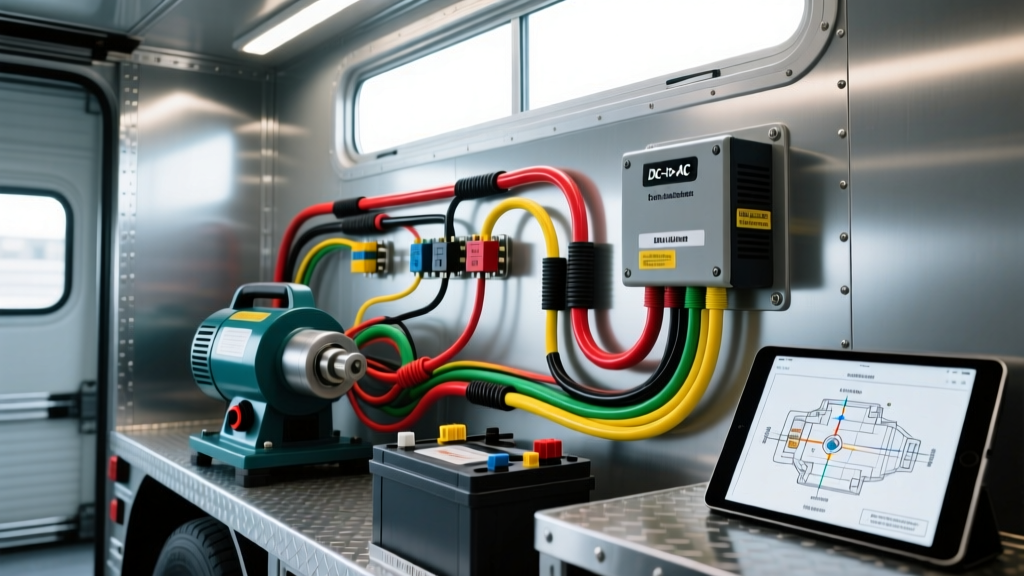
Integrating a Bench Grinder into a Mobile Automotive Workshop
For mobile mechanics, heavy-duty tow operators, and field service technicians, having onboard fabrication and prep tools is a massive upgrade. While portable angle grinders are common, a dedicated 120V AC bench grinder mounted in the utility bed of a Ford F-450 or Ram 4500 service truck offers superior stability for weld prep, rust removal, and bracket modification. However, powering an inductive AC motor load from a vehicle's 12V DC electrical system requires a precise wiring diagram for bench grinder integration to prevent voltage drops, inverter failures, and CAN-bus interference. This guide details the complete DC-to-AC electrical architecture required to safely run a 3/4 HP bench grinder off a mobile service truck's auxiliary power system.
Understanding the Power Requirements: Inductive Loads vs. Vehicle Alternators
Unlike resistive loads (such as work lights or heating elements), the induction motor inside a bench grinder requires a massive surge of current to overcome initial inertia. A standard 3/4 HP (559W) bench grinder typically draws 6 to 8 amps during continuous operation. However, the Locked Rotor Amps (LRA) or startup surge can easily reach 25 to 35 amps for a fraction of a second. If your mobile power system is not sized for this surge, the inverter will trigger a high-voltage or over-current fault, shutting down the circuit before the grinder wheel even reaches operating speed.
Sizing the Pure Sine Wave Inverter
To accommodate the 3000W+ startup surge of a 3/4 HP grinder, you must install a minimum 3000W Pure Sine Wave inverter. Modified sine wave inverters will cause the bench grinder motor to run hot, hum loudly, and potentially degrade the internal windings due to harmonic distortion. Furthermore, the truck's charging system must be evaluated. A factory 160A alternator leaves little headroom for a 250A DC draw. Upgrading to a high-output 300A alternator (such as those from Nations Starter & Alternator or Mechman) or utilizing a dedicated secondary auxiliary battery bank is mandatory for this modification.
DC Side: Vehicle Battery and Inverter Wiring Diagram
The DC side of the circuit is where most mobile workshop upgrades fail. Pulling 250 amps from a 12V system requires massive cable and impeccable termination. The wiring diagram for the DC feed routes directly from the auxiliary battery bank to the inverter's positive and negative bus bars, bypassing the vehicle's primary chassis ground to prevent overloading factory ground straps.
DC Cable Sizing and Voltage Drop Chart
Voltage drop is the enemy of high-amperage DC circuits. A 3% voltage drop at 12V equates to a 0.36V loss. If the inverter senses input voltage dropping below 10.5V during the grinder's startup surge, it will initiate a low-voltage disconnect (LVD). Use the following chart to select the correct AWG based on your one-way cable run distance:
| Cable Gauge (AWG) | Max Continuous Amps | Max Length (One-Way) for <3% Drop at 250A | Recommended Fuse |
|---|---|---|---|
| 1/0 AWG | 260A | 4 feet | 250A Class T |
| 2/0 AWG | 300A | 8 feet | 300A Class T |
| 3/0 AWG | 350A | 12 feet | 350A ANL |
| 4/0 AWG | 400A | 16 feet | 400A ANL |
Note: Always use fine-strand pure copper welding cable (SGT/SAE J1128) rather than solid copper building wire, as vehicle vibration will quickly fatigue and snap solid wire.
DC Termination and Routing Standards
According to standard automotive electrical practices outlined in Automotive Electricity and Electronics by James D. Halderman, high-current DC cables must be crimped using a hydraulic crimper with the correct hex die to ensure a cold-weld connection. Soldering large gauge battery cables is discouraged in high-vibration mobile environments because solder can wick into the wire strands, creating a brittle point that snaps under chassis flex. Seal all 2/0 AWG ring terminals with dual-wall, marine-grade adhesive heat shrink to prevent moisture intrusion and galvanic corrosion at the battery terminals.
AC Side: Wiring Diagram for Bench Grinder Receptacle
On the output side, the inverter generates 120V AC. Because a bench grinder is typically used in outdoor, potentially damp environments (such as an open utility bed or a mobile repair site), the AC wiring diagram must incorporate Ground Fault Circuit Interrupter (GFCI) protection and proper equipment grounding.
Receptacle Pinout and Wire Colors
We recommend wiring a NEMA 5-20R (20-Amp, 125V) receptacle box mounted securely to the truck's utility bed. Use 12 AWG THHN stranded wire pulled through liquid-tight flexible metallic conduit to protect against physical damage and grinding sparks.
- Hot (Line): Black 12 AWG wire connected to the brass terminal on the GFCI receptacle and the inverter's AC L1 output breaker.
- Neutral: White 12 AWG wire connected to the silver terminal on the GFCI receptacle and the inverter's AC N output bus.
- Equipment Ground: Green or bare 12 AWG wire connected to the green grounding screw on the receptacle. This must be bonded directly to the inverter's AC chassis ground terminal.
Chassis Grounding and EMI Suppression
Modern service trucks (2015 and newer) rely heavily on multiplexed CAN-bus networks (SAE J1939 for heavy-duty, ISO 15765 for light/medium). Induction motors like those in bench generators create severe back-Electromotive Force (back-EMF) and electromagnetic interference (EMI) when switched off. If the AC ground is not properly bonded to the truck's chassis, this EMI can couple into the vehicle's data lines, throwing phantom U-codes (e.g., U0001 High Speed CAN Communication Bus) or causing the instrument cluster to reset.
As detailed in the SAE J1113 Electromagnetic Compatibility standards, proper shielding and grounding are non-negotiable. To complete the wiring diagram for bench grinder integration, run a dedicated 4 AWG ground strap from the inverter's chassis ground lug directly to a clean, bare-metal point on the truck's main frame rail. Do not ground the inverter to the utility bed skin or aluminum tread plate, as the paint and hinges will create high resistance, forcing the return current through the truck's sensitive sensor grounds.
Step-by-Step Integration Procedure
- Disconnect the Vehicle Batteries: Isolate the primary and auxiliary battery banks before beginning any DC cable routing.
- Mount the Inverter: Secure the pure sine wave inverter to a structural crossmember using isolation dampeners to reduce high-frequency vibration transfer.
- Install the Class T Fuse: Mount a Class T fuse block within 18 inches of the auxiliary battery positive terminal. This is critical for short-circuit protection.
- Route DC Cables: Run the 2/0 AWG positive and negative cables through split loom tubing, securing them with P-clips every 12 inches. Keep DC cables at least 12 inches away from the truck's main wiring harness.
- Wire the AC GFCI Receptacle: Terminate the 12 AWG AC wires into the NEMA 5-20R GFCI receptacle and mount it in a weatherproof, die-cast aluminum box.
- Bond the Grounds: Connect the 4 AWG chassis ground strap from the inverter to the frame rail. Torque the frame bolt to 45 lb-ft and coat with dielectric grease.
- Test Voltage Drop: With the grinder running under load, use a digital multimeter to measure the voltage drop across the DC cables. A reading higher than 0.25V indicates poor crimps or undersized wire.
Troubleshooting the Mobile Grinder Circuit
Even with a flawless wiring diagram for bench grinder setups, mobile environments introduce unique failure modes. Use this decision tree to diagnose common issues:
| Symptom | Probable Cause | Diagnostic Fix |
|---|---|---|
| Inverter faults immediately when grinder is switched ON | Voltage sag triggering Low Voltage Disconnect (LVD) | Check auxiliary battery state of charge (SoC). Verify alternator output under load. Upgrade to 4/0 AWG cables if voltage drop exceeds 0.3V. |
| Grinder motor runs hot and hums loudly | Harmonic distortion from Modified Sine Wave inverter | Verify inverter output with an oscilloscope. Replace with a true Pure Sine Wave inverter to match utility grid power. |
| GFCI receptacle trips randomly during grinding | Ground loop or neutral-to-ground bond fault | Ensure the inverter's internal neutral-to-ground relay is functioning. Check for pinched THHN wires in the liquid-tight conduit causing micro-shorts. |
| Truck dash lights flicker or CAN-bus codes appear | Back-EMF from grinder motor coupling into data lines | Inspect the 4 AWG inverter chassis ground strap. Install an RC snubber circuit across the grinder's AC plug to suppress inductive kickback. |
Conclusion
Integrating a 120V bench grinder into a mobile service truck bridges the gap between a standard vehicle and a fully functional rolling workshop. By strictly adhering to this wiring diagram for bench grinder applications—prioritizing 2/0 AWG or larger DC feeds, pure sine wave inversion, and dedicated chassis grounding—you ensure reliable operation without compromising the truck's sensitive automotive electronics. For further reading on mobile power architectures and advanced DC-AC integration, the Victron Energy Wiring Unlimited Guide remains an indispensable resource for automotive electrical upfitters.