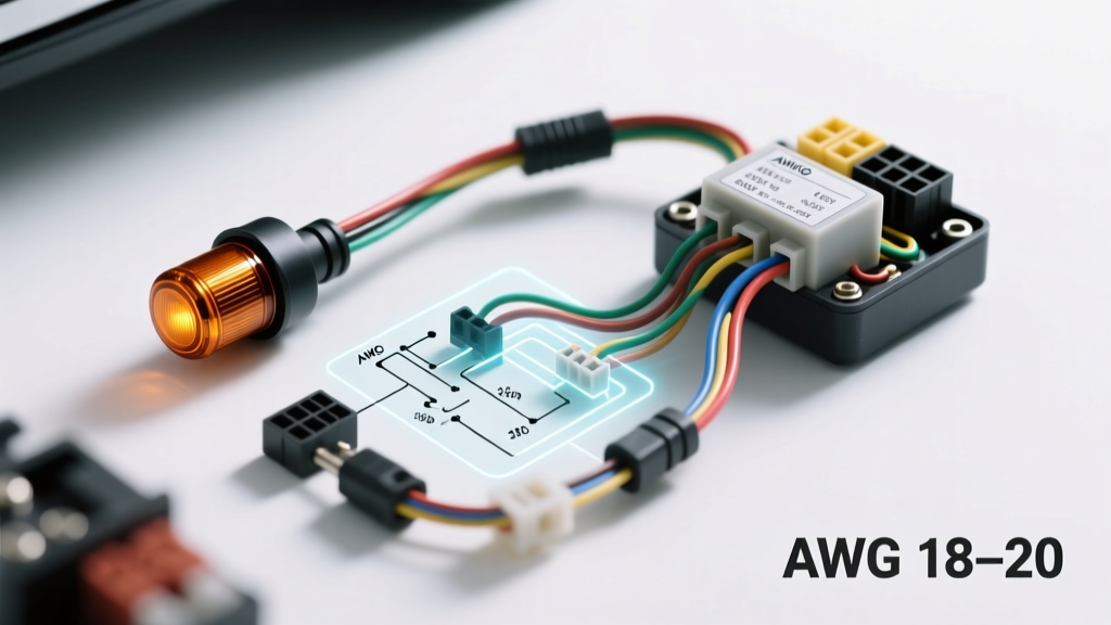
Understanding the 3-Wire Combined Brake and Turn Circuit
When fabricating a custom harness, restoring a classic truck, or integrating an aftermarket steering column, interpreting a 3 wire brake light turn signal wiring diagram is a fundamental automotive electrical skill. Unlike modern vehicles that utilize separated lighting systems or multiplexed CAN-bus networks, classic American automobiles, early SUVs, and many custom hot rods rely on a combined 3-wire circuit at the rear tail light housing. In this configuration, the physical tail light pigtail features three distinct wires: a dedicated chassis ground, a running/tail light feed, and a combined stop/turn signal feed.
The complexity of the 3 wire brake light turn signal wiring diagram lies not at the tail light itself, but within the steering column turn signal switch. The switch must seamlessly interrupt the constant 12V brake light feed and replace it with the pulsing 12V flasher feed when the turn signal lever is engaged. Failing to wire this logic correctly results in brake lights that refuse to cancel, turn signals that stay illuminated solid, or dangerous backfeed conditions that illuminate the dash cluster when the brakes are applied.
Wire Gauge Specifications and Material Requirements
Before cutting any wire, you must select the correct gauge and insulation type. According to SAE J578 and SAE J1128 standards, automotive wiring should utilize cross-linked polyethylene (SXL or GXL) insulation for high-temperature resistance in engine bays and frame rails. Standard PVC wire will become brittle and crack over time due to chassis vibration and heat cycling.
| Circuit Segment | Incandescent Draw | LED Draw | Recommended AWG | Wire Type |
|---|---|---|---|---|
| Main Brake Switch Feed | 8.5 Amps | 1.2 Amps | 14 AWG | GXL Cross-linked |
| Left/Right Stop/Turn Feed | 4.2 Amps | 0.6 Amps | 16 AWG | GXL Cross-linked |
| Tail/Running Light Feed | 3.0 Amps | 0.4 Amps | 16 AWG | GXL Cross-linked |
| Tail Light Chassis Ground | 8.5 Amps | 1.2 Amps | 14 AWG | GXL Cross-linked |
Note: While LED lighting drastically reduces amperage draw, we still mandate 16 AWG for the physical tail light pigtails to ensure mechanical durability and prevent voltage drop over long frame rail runs.
Step-by-Step 3 Wire Brake Light Turn Signal Wiring Diagram Execution
Step 1: Establishing a Chassis Ground Network
The most common cause of tail light failure in combined circuits is a high-resistance ground. In a 3-wire tail light housing, the ground wire does not simply connect to the nearest bolt. You must establish a dedicated ground network.
- Prepare the Surface: Use a wire wheel or 80-grit sandpaper to remove all paint, powder coat, and rust from the chassis grounding point near the rear crossmember.
- Terminate the Wire: Strip 14 AWG black wire and crimp a heavy-duty, non-insulated ring terminal using a ratcheting crimp tool. Solder the connection for maximum vibration resistance.
- Hardware Selection: Secure the ring terminal using a Grade 8 or stainless steel bolt, paired with a star washer between the terminal and the bare metal to bite into the chassis and prevent loosening.
- Seal the Connection: Apply a dab of dielectric grease over the terminal to prevent galvanic corrosion, which will slowly increase resistance over time and cause the 'backfeed' symptoms detailed later in this guide.
Step 2: Integrating the Turn Signal Switch and Flasher Relay
The heart of the 3 wire brake light turn signal wiring diagram is the turn signal switch, typically a 7-pin or 9-pin connector on classic GM and Ford columns. The switch requires three specific rear-bound wires: Dark Green (Right Stop/Turn), Yellow (Left Stop/Turn), and White or Light Blue (Brake Switch Feed In).
For the flasher relay, you must use an electronic 3-pin flasher if you are running LEDs, or a standard thermal flasher for incandescent bulbs. A 3-pin flasher utilizes the following pinout:
- Pin B (Battery): Connects to a switched 12V ignition source via a 10A inline fuse.
- Pin L (Load): Connects to the flasher feed wire routing up to the steering column turn signal switch.
- Pin P (Pilot): Connects to the dashboard indicator bulb. If your dash uses separate left/right indicators, you will need to wire diodes to prevent cross-illumination.
When the brake pedal is depressed, 12V travels from the brake light switch into the turn signal switch. If the turn signal is OFF, the switch routes this 12V out to both the Left and Right Stop/Turn wires. If the turn signal is ON, the internal switch mechanism physically breaks the brake feed to the active side, replacing it with the pulsing 12V from the flasher relay's 'L' terminal. As noted in MAD Electrical's turn signal technical guide, ensuring the column switch receives a clean, unspliced brake feed is critical for safe operation.
Step 3: Terminating the 3-Wire Tail Light Pigtails
At the rear of the vehicle, you will interface the main harness with the tail light housings. Whether using bullet connectors, Weather-Pack seals, or Deutsch DT connectors, moisture ingress is the enemy.
- Color Coding: Adhere to standard OEM color codes to simplify future diagnostics. Use Brown for the Tail/Running light, Dark Green for the Right Stop/Turn, and Yellow for the Left Stop/Turn.
- Connector Selection: Avoid standard vinyl butt connectors. Use 3:1 dual-wall adhesive-lined heat shrink crimp connectors. The inner adhesive melts during the shrinking process, creating a waterproof environmental seal that prevents capillary action from drawing water into the copper strands.
- Strain Relief: Zip-tie the harness to the frame rail exactly 4 inches before the connector. This creates a drip loop and ensures that chassis flex and suspension travel do not pull directly on the electrical terminals.
Troubleshooting Combined Circuit Backfeed and Hyper-Flashing
Even with a perfect 3 wire brake light turn signal wiring diagram, real-world variables can introduce faults. Use this diagnostic decision tree to isolate issues:
- Symptom: Turn signal activates, but the opposite side tail light dims or the dash lights illuminate faintly.
Cause: High-resistance ground at the tail light housing. The current seeks an alternative path to ground, backfeeding through the running light circuit.
Fix: Run a dedicated 14 AWG ground wire directly from the tail light housing to the main chassis ground bus. Do not rely on the housing bolts alone. - Symptom: Turn signals flash rapidly (hyper-flashing), but bulbs/LEDs function.
Cause: A thermal flasher relay relies on the heat generated by high amperage draw (typically 4+ amps) to bend the internal bimetallic strip. LEDs draw less than 1 amp, failing to trigger the thermal cycle.
Fix: Replace the thermal flasher with an electronic LED flasher relay (e.g., Tridon EL12 or equivalent) that uses an internal timer circuit rather than thermal resistance. - Symptom: Brake lights stay on constantly, even when the pedal is released.
Cause: The brake light switch at the pedal arm is misadjusted, or the internal contacts of the steering column turn signal switch are fused together due to a previous short circuit.
Fix: Adjust the pedal pushrod clearance. If the pedal switch is functioning, replace the column turn signal switch assembly.
Expert Insights on LED Load Equalizers
If your vehicle's Body Control Module (BCM) or factory flasher unit cannot be swapped for an electronic relay, you must install load equalizers (resistors) to simulate incandescent amperage draw. For a standard 3-wire combined circuit, you will need a 50-Watt, 6-Ohm ceramic resistor wired in parallel with the Stop/Turn wire on each side of the vehicle.
Warning: These resistors generate extreme heat—often exceeding 300°F (150°C) during sustained use. They must be bolted directly to a metal chassis surface using stainless steel hardware. Never zip-tie a load resistor to a plastic bumper cover, wire loom, or painted surface, as it will melt the surrounding materials and create a severe fire hazard. For comprehensive harness routing and safety protocols, refer to the Painless Performance Wiring Guide for best practices in high-current aftermarket lighting integration.
By strictly adhering to proper AWG sizing, utilizing environmental connectors, and understanding the internal logic of the turn signal switch, your 3-wire combined lighting system will provide reliable, DOT-compliant visibility for years to come.