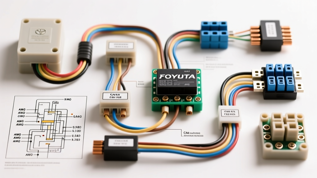
Upgrading the Toyota Camry: Navigating the Multiplex Network
When executing an upgrade or modification project on a Toyota Camry (specifically the XV40 and XV50 generations), relying on a generic 12-volt assumption is a recipe for damaging the Body ECU. Modern Camry platforms utilize a sophisticated Multiplex Communication System (MPX) and CAN-bus architecture to manage everything from head unit illumination to daytime running light (DRL) duty cycles. To perform clean, reliable aftermarket stereo and LED lighting installations, you must reference the exact Toyota Camry electrical wiring diagram for your specific chassis code.
This guide provides the critical OEM pinouts, wire gauge (AWG) requirements, and pulse-width modulation (PWM) bypass strategies necessary for high-end automotive modifications. Whether you are integrating a digital signal processor (DSP) or retrofitting high-output LED headlight assemblies, understanding the OEM harness topology is mandatory to avoid triggering diagnostic trouble codes (DTCs) or causing parasitic battery drains.
Head Unit & Amplifier Integration: OEM Connector Pinouts
The factory radio in non-JBL equipped Camry models terminates into two primary Yazaki connectors: the 10-pin E3 (Power/Accessory) and the 20-pin E2 (Speaker/Signal) block. When splicing into the OEM harness for an aftermarket head unit or a line-out converter (LOC), always use T-taps or, preferably, cut-and-solder connections sealed with dual-wall heat shrink. Toyota TechInfo service manuals dictate that wire splices must maintain the original circuit's current-carrying capacity and vibration resistance to prevent intermittent signal loss.
E3 Connector (10-Pin Power & Accessory)
| Pin | Wire Color | Function | Recommended AWG |
|---|---|---|---|
| 1 | White/Red | +B (Constant 12V Battery) | 14 AWG |
| 2 | Gray | ACC (Switched 12V Ignition) | 14 AWG |
| 3 | Brown | GND (Chassis Ground) | 14 AWG |
| 4 | Green/White | +I (Illumination Dimmer) | 18 AWG |
| 5 | Blue/White | AMP (Amplifier Turn-On) | 18 AWG |
E2 Connector (20-Pin Speaker Outputs)
Toyota utilizes a standardized color code for speaker outputs across most of its North American lineup. Note that OEM speaker wire is typically 18 AWG. For aftermarket amplifiers, run new 16 AWG OFC (Oxygen-Free Copper) speaker wire directly from the amp to the door harness boots to minimize resistance and improve damping factor.
- Front Left (+/-): Pink / Purple
- Front Right (+/-): Light Blue / Blue
- Rear Left (+/-): Black / Yellow
- Rear Right (+/-): Red / White
Steering Wheel Controls (SWC) and CAN-Bus Integration
Older vehicles used a simple resistor-ladder network for steering wheel audio controls. However, the Gen 6 and Gen 7 Camry routes SWC signals through the clock spring directly into the Body ECU via the MPX network. You cannot simply tap a single wire to read resistance changes. Instead, you must use a CAN-bus interface module (such as the Maestro RR or PAC RP4-TY11) that plugs inline with the OEM data lines. This module translates the multiplexed digital commands into analog resistance signals or secondary data packets that aftermarket head units (like Pioneer, Kenwood, or Alpine) can interpret without throwing a check engine light.
Amplifier Power Routing and Grounding Protocols
Running main power wire from the battery to the trunk requires navigating the Camry's firewall. The primary harness grommet is located behind the driver-side kick panel. Use a fiberglass fish tape and apply silicone dielectric grease to lubricate the 4 AWG or 8 AWG power wire through the rubber grommet. Never pierce the grommet with a screwdriver; instead, use a specialized grommet punch tool to create a clean slit that will seal around the wire, preventing exhaust fumes and moisture from entering the cabin.
According to SAE J1292 standards for automotive electrical wiring, overcurrent protection must be installed within 18 inches of the power source. Install an 80A ANL fuse holder on the positive battery terminal before routing the cable. The Camry's OEM battery terminals are often lead-clad or undersized for high-current aftermarket demands. When installing systems exceeding 800W RMS, replace the OEM positive terminal with a military-spec brass terminal or install a dedicated fuse distribution block directly on the positive post to accommodate multiple 4 AWG runs without overloading the factory alternator sense wire.
For the amplifier ground, locate a factory chassis bolt in the trunk pan. Remove the bolt, sand the contact area down to bare, shiny metal using 80-grit sandpaper, and secure the ring terminal. Torque the bolt to 10-12 Nm and coat the terminal with petroleum jelly or dielectric grease to prevent galvanic corrosion.
LED Lighting Retrofits: Bypassing PWM DRL Circuits
One of the most common modification projects for the Camry is upgrading the halogen DRL and headlight assemblies to LEDs. The Camry's Body ECU controls the DRL circuit using Pulse Width Modulation (PWM). By rapidly switching the 12V signal on and off at a specific duty cycle (typically around 50-70% at 200Hz), the ECU reduces the average voltage to the halogen bulbs, extending their lifespan and reducing power draw.
Because LEDs switch states in microseconds, this PWM signal causes severe, visible flickering when applied to LED driver boards. On higher trim levels (XLE, Touring) equipped with the multi-information display (MID), installing LEDs without proper load resistors or decoders will trigger a 'Check Headlight System' warning on the dash. The Body ECU monitors the voltage drop across the lighting circuit; if the threshold isn't met, it logs a DTC and disables the circuit to prevent perceived short-circuit damage. To resolve this, you must wire an anti-flicker PWM decoder or a high-capacitance filter in parallel with the LED driver.
Anti-Flicker Decoder Wiring Sequence
- Disconnect the negative battery terminal to prevent shorting the Body ECU.
- Unplug the OEM H11 or 9005 headlight connector.
- Plug the anti-flicker decoder's male input into the OEM harness.
- Plug the LED driver's male connector into the decoder's female output.
- Secure the decoder's inline capacitor (usually 4700µF to 10000µF) to the chassis using a zip tie, ensuring it does not rest against the hot radiator or exhaust manifolds.
- Reconnect the battery and test the DRL operation via the headlight stalk.
Real-World Modification Failure Modes & Troubleshooting
Even with a perfect Toyota Camry electrical wiring diagram, aftermarket modifications can introduce complex electrical gremlins. Below are common failure modes encountered during Camry audio and lighting builds:
- Symptom: Parasitic battery drain overnight after stereo installation.
Cause: The aftermarket head unit or CAN-bus interface is failing to enter 'sleep' mode, keeping the MPX network awake.
Fix: Verify the interface module's firmware is updated. Ensure the ACC wire is not back-feeding voltage into the CAN-bus sleep line. Use a multimeter to measure the parasitic draw at the battery; it should drop below 50mA after 15 minutes. - Symptom: High-pitched alternator whine in the audio system that scales with engine RPM.
Cause: Ground loop caused by differing chassis potentials between the head unit and the trunk-mounted amplifier.
Fix: Ensure both the head unit and amplifier are grounded to the same bare-metal chassis plane. Use twisted-pair RCA cables with high braided shielding, and route RCA signal cables down the center console, strictly separating them from the 12V power wires running along the driver's side rocker panel. - Symptom: Hyper-flashing turn signals after installing LED bulbs.
Cause: The Body ECU detects a lower current draw from the LEDs and assumes a blown bulb.
Fix: Wire 50W 6-ohm load resistors in parallel with each LED turn signal bulb. Mount the resistors to a metal heat sink or chassis bracket, as they will generate significant heat during sustained use.
For comprehensive, factory-verified schematics and connector cavity views, always cross-reference your specific VIN with the official Crutchfield Vehicle Database or OEM service portals before cutting a single wire. Proper planning and adherence to OEM wiring topologies ensure your modification project enhances the vehicle without compromising its electrical integrity.