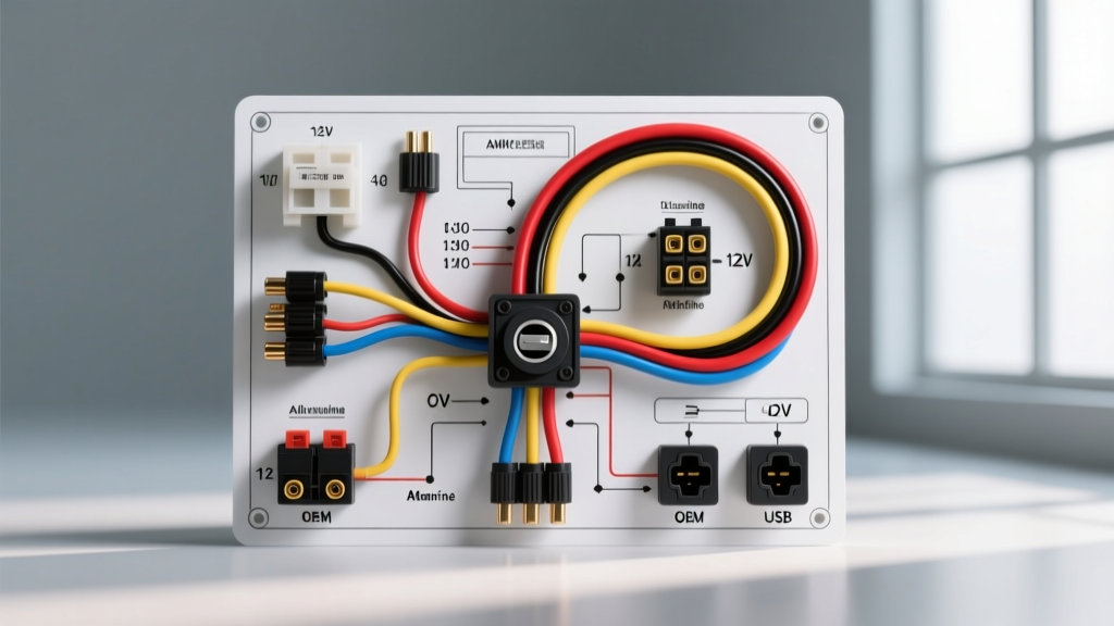
Understanding the Universal Car Lighter Wiring Diagram
The 12V accessory socket, historically known as the cigarette lighter receptacle, is the most ubiquitous power source in modern vehicles. However, as automotive enthusiasts increasingly rely on high-draw accessories like portable air compressors, thermoelectric coolers, and power inverters, the limitations of factory wiring become apparent. Before selecting an upgrade, it is critical to understand the foundational car lighter wiring diagram and the physical anatomy of the receptacle.
According to the SAE J563 standard, which governs the dimensions and electrical contacts of cigarette lighters, the universal pinout remains consistent across nearly all manufacturers. The center contact pin at the base of the socket is the positive (+12V) feed. The outer metallic cylinder, featuring internal spring-loaded bi-metallic side clips, serves as the negative ground return path. In OEM applications, the positive feed is typically routed through the ignition switch or an accessory relay, meaning the socket only receives power when the key is in the "ACC" or "ON" position. This prevents parasitic battery drain when the vehicle is parked.
OEM Wire Color Codes and Circuit Identification
When tapping into or replacing a factory harness, identifying the correct wires is essential to avoid short circuits. While aftermarket kits universally use Red for +12V and Black for Ground, OEM manufacturers utilize specific color codes that vary by make:
- Ford / Lincoln: Typically uses a Light Green wire with a Yellow stripe for the +12V switched power, and a solid Black wire for chassis ground.
- General Motors (Chevy/GMC): Often utilizes a solid Orange wire for the +12V accessory feed (originating from the RAP - Retained Accessory Power module) and a Black wire for ground.
- Toyota / Lexus: The "CIG" (Cigarette) or "ACC" circuit usually features a Gray or Blue/Red striped wire for power, with a White/Black striped wire for ground.
Always verify the circuit with a digital multimeter (DMM) before cutting or splicing. Probe the suspected power wire with the ignition ON; you should read 12.4V to 14.4V (if the alternator is charging). Turn the ignition OFF; the voltage should drop to 0V on a switched circuit.
Product Comparison: Selecting the Right 12V Socket
Not all 12V receptacles are built equally. When planning an upgrade based on your car lighter wiring diagram, you must match the socket's physical and electrical characteristics to your intended load. Below is a comparison of the three primary socket categories available on the market.
Category 1: Standard OEM-Style Ceramic Sockets
These are direct replacements for factory units. They feature a ceramic or high-temperature phenolic resin housing designed to withstand the intense heat generated by traditional cigarette lighter heating elements. They utilize standard 0.250-inch (6.3mm) female spade connectors on the rear.
- Max Continuous Draw: 10A to 12A (120W - 144W).
- Built-in Protection: Many OEM sockets feature an integrated bi-metallic thermal strip that physically breaks the connection if the internal temperature exceeds safe thresholds, acting as a secondary failsafe to the vehicle's fuse box.
- Best Use Case: Dashcams, GPS units, phone chargers, and low-draw LED interior lighting.
- Failure Mode: High-draw devices like air compressors will cause the side springs to overheat, lose tension, and result in voltage drop or melted plastic bezels.
Category 2: Heavy-Duty Marine / Bilge Sockets
Designed for harsh environments and continuous high-amperage draws, marine sockets ditch the traditional side-spring ground design for a robust, threaded screw-terminal or heavy ring-terminal connection. They feature weatherproof rubber caps and are constructed from UV-resistant, glass-filled nylon or anodized aluminum.
- Max Continuous Draw: 20A to 30A (240W - 360W).
- Wiring Requirement: Requires upgrading the car lighter wiring diagram to include 12 AWG or 10 AWG wire and an inline MAXI fuse or a dedicated relay circuit.
- Best Use Case: Portable air compressors, 150W+ power inverters, 12V winches, and marine bilge pumps.
- Failure Mode: If installed in a standard dashboard knockout hole without proper heat shielding, the heavy gauge wires can stress the dashboard mounting bracket due to stiffness.
Category 3: USB-Integrated Step-Down Sockets
These modern replacements feature a standard 12V barrel alongside integrated USB-A and USB-C ports. They contain an internal buck converter (step-down transformer) that drops the 14.4V alternator output down to a stable 5V (or up to 20V for USB-C Power Delivery).
- Max Continuous Draw: 10A on the 12V barrel; 3A to 5A on the USB circuits.
- Wiring Requirement: Standard 14 AWG or 16 AWG wire. However, these units are highly sensitive to voltage spikes and require a clean power source. Using a relay with a flyback diode is recommended if the vehicle has a noisy alternator.
- Best Use Case: Daily drivers requiring fast-charging for modern smartphones, tablets, and laptops without the need for bulky 12V-to-USB adapters.
Technical Selection Matrix: Wire, Fuse, and Terminal Specs
When modifying your vehicle's electrical system, adhering to Littelfuse Automotive Circuit Protection guidelines and SAE standards is non-negotiable. Use the matrix below to select the correct components for your chosen socket type.
| Socket Category | Min. Wire Gauge (AWG) | Recommended Fuse Type & Rating | Terminal / Connector Type | Relay Required? |
|---|---|---|---|---|
| Standard OEM Ceramic | 14 AWG (or 12 AWG for runs > 10ft) | ATO/ATC Blade - 15A Max | 0.250" Insulated Female Spade | No (Use OEM ACC circuit) |
| Heavy-Duty Marine (20A) | 12 AWG Copper | MAXI Blade - 20A or 25A | #8 or #10 Ring Terminal (Screw mount) | Yes (Triggered by ACC) |
| Heavy-Duty Marine (30A) | 10 AWG Copper | MAXI Blade - 30A or MIDI Fuse | #8 Ring Terminal (Screw mount) | Yes (Triggered by ACC) |
| USB-Integrated Step-Down | 16 AWG or 14 AWG | Low-Profile Mini - 10A | 0.250" Insulated Spade or Quick-Splice | No (Use OEM ACC circuit) |
Wiring Best Practices and Termination
The most common cause of 12V socket fires is not an overloaded circuit, but rather poor termination leading to high contact resistance. When high current passes through a high-resistance connection, it generates immense heat (Power = I²R).
When executing your car lighter wiring diagram, adhere to these professional termination standards:
- Avoid Solder on Flex Points: While soldering provides a solid electrical bond, it creates a rigid point on stranded copper wire. In a vehicle, vibration will cause the wire to fatigue and snap exactly at the edge of the solder joint. Always use high-quality, ratcheting crimp tools for insulated spade and ring terminals.
- Use Adhesive-Lined Heat Shrink: After crimping, apply 3M or equivalent adhesive-lined (dual-wall) heat shrink tubing. The inner meltable adhesive seals out moisture and prevents corrosion, which is especially critical for ground connections bolted to the chassis.
- Chassis Ground Preparation: If your wiring diagram requires grounding directly to the vehicle chassis rather than running a dedicated ground wire back to the battery, you must sand away the paint, primer, and E-coat down to bare metal. Secure the ring terminal with a stainless steel bolt and a star washer, then coat the area with dielectric grease to prevent oxidation.
- Relay Integration for High Draws: If you are installing a 20A marine socket, do not run it directly through the ignition switch. The ignition switch contacts are not rated for continuous 20A loads and will melt. Instead, use the existing low-amperage ACC wire to trigger the coil (Pins 85 and 86) of a standard Bosch-style 4-pin automotive relay. Run a dedicated 12 AWG fused line directly from the battery to Pin 30, and feed the new socket from Pin 87.
Troubleshooting Common 12V Socket Failures
Even with a perfect installation, 12V accessory circuits can develop faults. Refer to this diagnostic decision tree when troubleshooting:
- Symptom: Accessory plugs in but receives no power.
- Check 1: Test the center pin with a DMM. If 0V, check the fuse panel (CIG, ACC, or PWR OUTLET fuses).
- Check 2: If the fuse is blown, inspect the accessory plug. Many cheap aftermarket plugs use weak side springs that collapse and bridge the center positive pin to the outer negative shell, causing a dead short.
- Symptom: Accessory works, but cuts out under heavy load (e.g., air compressor stalls).
- Check 1: Perform a voltage drop test. Place your DMM probes on the battery positive terminal and the center pin of the socket while the compressor is running. A reading above 0.5V indicates excessive resistance in the wiring or a failing OEM socket spring.
- Check 2: The OEM socket's internal thermal limiter may be tripping. Allow the socket to cool for 5 minutes. If power returns, you must upgrade to a Heavy-Duty Marine socket.
- Symptom: Battery dies overnight after installing a new USB socket.
- Fix: The new socket was likely wired to a constant B+ (Battery) source instead of a switched ACC source. Consult the vehicle's wiring diagram to locate a fuse that only shows continuity when the ignition is ON, or install a relay to isolate the socket when the vehicle is off.
Conclusion
Upgrading your vehicle's 12V power capabilities requires more than simply plugging in a new accessory. By understanding the core car lighter wiring diagram, respecting AWG and fuse limitations, and selecting the correct socket category for your specific amperage needs, you can safely power high-draw electronics without risking electrical fires or parasitic battery drains. For further reading on automotive circuit protection and wire gauge ampacity charts, consult resources from AutoShop 101 Electrical Circuits and your vehicle manufacturer's specific service manual.