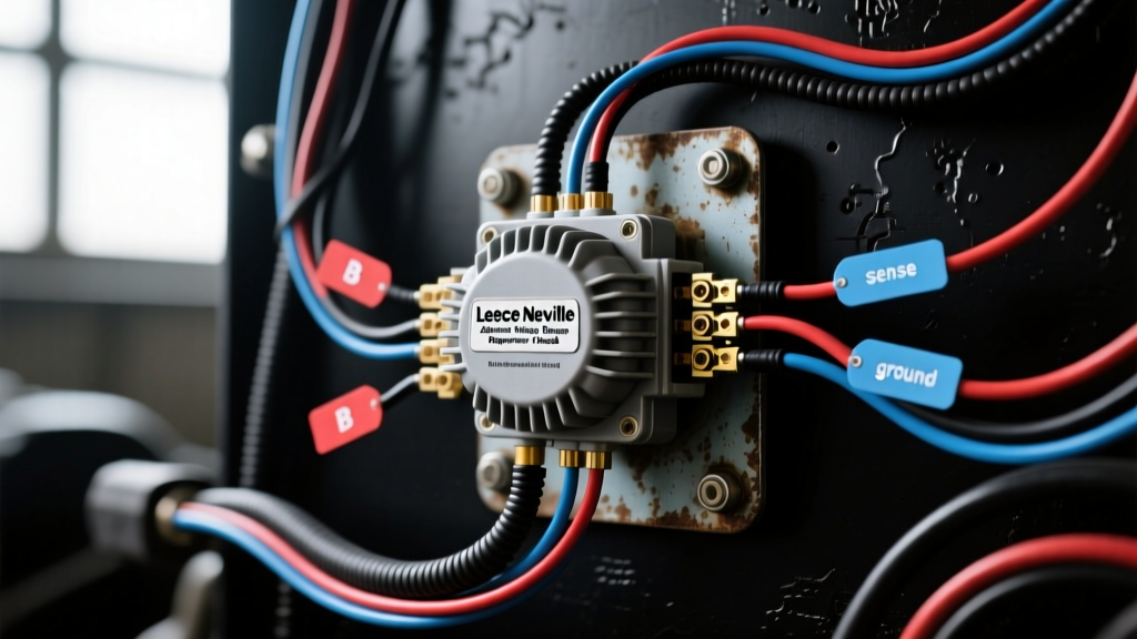
Demystifying the Leece Neville Alternator Wiring Diagram
If you are stepping into the world of heavy-duty trucks, commercial fleets, marine electrical systems, or high-end off-road builds, you will inevitably encounter a Leece Neville alternator. Now manufactured under the Prestolite Electric umbrella, Leece Neville alternators—particularly the legendary 28SI, 36SI, and 4000 series—are the undisputed workhorses of high-amp charging. However, for a beginner, staring at a multi-pin regulator connector, massive output studs, and heavy-duty mounting ears can be intimidating. This beginner-friendly guide breaks down the fundamental Leece Neville alternator wiring diagram into actionable, easy-to-understand steps, ensuring your charging system is safe, efficient, and reliable.
Core Anatomy: B+, Ground, and the Regulator Plug
Before cutting any wire or crimping any terminals, you must understand the physical interface of a standard internally regulated Leece Neville alternator. Unlike older passenger car alternators that rely on simple single-wire excitation, heavy-duty Leece Neville units require a dedicated control harness to manage high-amperage output safely across varying engine RPMs and heavy electrical loads.
The Heavy-Duty Output (B+) and Ground (B-)
The B+ Terminal is the main output stud where the generated DC current exits the alternator. On most 28SI and 36SI models, this is a heavy-duty copper stud, typically threaded at 5/16"-24 UNF or 3/8"-16 UNC. This terminal must connect directly to the vehicle's battery positive post or the main positive busbar. The Ground (B-) is primarily achieved through the alternator's massive cast-iron or aluminum mounting ears mating to the engine block. However, for high-amp applications (160A and above), relying solely on case grounding is a beginner mistake. You must utilize the dedicated ground pad (often an M8 or M10 threaded hole on the rear housing) to run a dedicated ground strap back to the battery negative or engine block ground boss.
The 3-Pin / 4-Pin Regulator Connector
The brain of the alternator is the internal voltage regulator, which interfaces with the vehicle via a multi-pin connector. The most common configuration for beginner swaps and standard heavy-duty applications is the 3-pin Metri-Pack 280 style connector. Understanding these three pins is the key to mastering the Leece Neville alternator wiring diagram.
| Pin / Letter | Function | Recommended Wire Color | AWG Size | Destination / Purpose |
|---|---|---|---|---|
| Pin 1 (I / R) | Ignition / Excite | Red or Pink | 16 - 14 AWG | Switched 12V/24V ignition source. Wakes up the regulator. |
| Pin 2 (S) | Battery Sense | Orange or Yellow | 14 - 12 AWG | Direct to Battery Positive. Reads true system voltage. |
| Pin 3 (T / F) | Tachometer / Fault | White or Gray | 18 - 16 AWG | AC tap for tachometer signal or relay trigger (Optional). |
Deep Dive on Pin 1 (Excite): The regulator requires a small voltage signal to turn on. If you wire this to a constant 12V source, the alternator will drain your battery when the engine is off. It must be wired to an ignition-switched circuit. If your dashboard uses a charge indicator light (idiot light), you can wire Pin 1 through the bulb. The bulb provides the initial resistance and current needed to excite the rotor field. If you are not using a dash light, you must install a 10-ohm to 50-ohm, 2-watt resistor in parallel with the ignition wire to prevent backfeeding.
Deep Dive on Pin 2 (Sense): This is the most critical wire for voltage regulation. The Sense wire tells the regulator what the battery is actually experiencing. If you simply jumper the Sense pin to the B+ output stud on the back of the alternator, the regulator will read the voltage at the alternator, not the battery. Because heavy cables experience voltage drop under high loads, the battery might only be receiving 12.8V while the alternator pushes 14.4V. The regulator will overcompensate, leading to overcharging and boiled batteries. Always run the Sense wire directly to the battery positive terminal or the main starter solenoid post.
Wire Gauge (AWG) and Routing Fundamentals
Heavy-duty alternators push massive amounts of current. Using undersized wire on the B+ circuit will result in severe voltage drop, melted insulation, and potentially catastrophic electrical fires. According to SAE International Standards and marine electrical codes, you must size your B+ cable based on the alternator's maximum continuous output and the total length of the cable run (positive and negative combined).
| Alternator Output (Amps) | Run Length (Under 5 ft) | Run Length (5 ft - 10 ft) | Run Length (10 ft - 15 ft) |
|---|---|---|---|
| 100A - 130A | 4 AWG | 2 AWG | 1 AWG |
| 140A - 160A | 2 AWG | 1 AWG | 1/0 AWG |
| 170A - 200A | 1 AWG | 1/0 AWG | 2/0 AWG |
| 220A - 250A+ | 1/0 AWG | 2/0 AWG | 3/0 AWG |
Note: Always use 100% pure copper, stranded marine-grade wire (Type 3) for heavy-duty applications. Copper-clad aluminum (CCA) wire has higher resistance and is unsafe for high-amp alternator B+ runs.
Step-by-Step Wiring Walkthrough for Beginners
Follow this structured sequence to ensure your Leece Neville alternator is wired safely and correctly the first time.
- Physical Mounting and Case Grounding: Bolt the alternator to the engine bracket. Ensure the mounting surfaces are bare metal, free of paint, rust, and grease. Scrape the metal clean to ensure a solid case ground. Install a dedicated 4 AWG ground strap from the alternator's rear ground lug to the engine block.
- B+ Cable Routing and Overcurrent Protection: Fabricate your main B+ cable using the AWG chart above. Use adhesive-lined heat shrink over heavy-duty closed-barrel ring terminals. Critical Safety Step: You must install a high-amperage fuse (such as a Mega Fuse or ANL Fuse) on the B+ wire within 18 inches of the battery positive terminal. Littelfuse Automotive Circuit Protection guidelines dictate that unprotected B+ cables can weld themselves to the chassis in the event of a short circuit, causing an immediate fire. Size the fuse slightly above the alternator's max output (e.g., a 200A fuse for a 160A alternator).
- Control Harness Fabrication: Build the 3-pin pigtail harness. Use a proper Metri-Pack crimping tool to ensure the terminal barbs lock securely into the plastic connector housing. Wrap the harness in split loom or Tesa tape to protect against engine heat and abrasion.
- Connecting the Excite and Sense Wires: Route the Sense wire (Pin 2) away from high-voltage ignition coils and alternator stator housings to prevent electromagnetic interference (EMI). Connect it directly to the battery positive post. Connect the Excite wire (Pin 1) to a clean, switched 12V source that only powers when the ignition key is in the 'ON' or 'RUN' position.
- Pre-Flight Voltage Check: Before starting the engine, use a digital multimeter. Verify that the B+ stud has battery voltage (12.6V). Turn the key to 'ON' (without cranking) and verify that the Excite wire at the plug is receiving 12V. Finally, verify the Sense wire reads battery voltage.
Real-World Troubleshooting: Symptom-Cause-Fix
Even with a perfect wiring diagram, beginners often encounter issues during initial startup. Use this decision tree to diagnose common Leece Neville charging anomalies.
- Symptom: Alternator whining loudly, battery overcharging to 15.5V or higher, headlights surging in brightness.
- Cause: The Sense wire (Pin 2) is disconnected, broken, or incorrectly jumpered to the B+ stud.
- Fix: The regulator has lost its reference voltage and is defaulting to maximum output. Reroute the Sense wire directly to the battery positive terminal.
- Symptom: Zero charging output at idle. Alternator only begins charging if the engine is revved past 2000 RPM, and it drops out when returning to idle.
- Cause: Missing or weak Excite voltage on Pin 1. The internal regulator is not receiving the initial current required to energize the rotor field.
- Fix: Check the ignition-switched 12V feed. If using a dash indicator bulb, ensure the bulb is not burnt out and is the correct resistance (typically a 194 or 168 bulb). Add a parallel resistor if necessary.
- Symptom: Alternator case is extremely hot to the touch, and the B+ cable is melting near the ring terminal.
- Cause: High resistance connection at the B+ stud or undersized wire gauge for the specific run length.
- Fix: Inspect the ring terminal crimp. If it was crimped with standard pliers instead of a heavy-duty hydraulic or mechanical crimper, the copper strands are loose, creating resistance and heat. Cut, re-crimp with the proper tool, and seal with adhesive heat shrink.
- Symptom: Parasitic battery drain overnight, vehicle won't start the next morning.
- Cause: The Excite wire (Pin 1) is wired to a constant 12V source instead of a switched ignition source, keeping the internal regulator awake and drawing current from the battery.
- Fix: Use a test light or multimeter to confirm the Excite wire loses all voltage when the ignition key is removed. Rewire to a proper switched circuit.
Final Thoughts on Heavy-Duty Charging
Wiring a Leece Neville alternator does not have to be a daunting task reserved for master diesel technicians. By respecting the fundamental rules of heavy-duty electrical flow—proper AWG sizing, dedicated grounding, accurate sense routing, and rigorous overcurrent protection—you can build a charging system that will reliably power winches, massive audio amplifiers, commercial lighting arrays, and RV appliances for years to come. Always double-check your pinouts against the specific data plate on your alternator housing, as variations exist between the 28SI, 36SI, and 4000 series models.