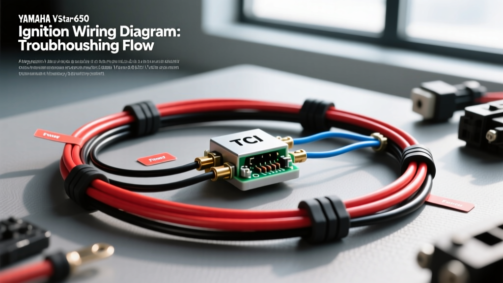
Yamaha V-Star 650 (XVS650) TCI Ignition System Overview
The Yamaha V-Star 650 (XVS650 Drag Star/Custom) utilizes a Transistor Controlled Ignition (TCI) system to manage spark timing and dwell for its 649cc V-twin engine. Unlike older points-based systems, the V-Star's TCI relies on a magnetic pulse generator (pickup coil) mounted near the flywheel to signal the ignition control unit. When diagnosing a no-spark condition, intermittent stalling, or a failure to crank, referencing the Yamaha V Star 650 ignition wiring diagram is critical. This guide provides a step-by-step troubleshooting flow, moving from main power verification down to the TCI logic gates and ignition coil primary circuits.
Core Ignition Wiring Matrix & Specifications
Before connecting your digital multimeter (DMM), familiarize yourself with the OEM wire color codes and American Wire Gauge (AWG) specifications used in the V-Star 650 ignition harness. Yamaha adheres to strict color-coding, but always verify with a wiring diagram for your specific year, as sub-harness revisions occurred between the 1998-2003 and 2004-2011 production runs.
| Circuit Function | Wire Color Code | AWG Size | Connector / Pin Location |
|---|---|---|---|
| Main Switched 12V Power | Red/White (R/W) | 14 AWG (2.0mm²) | Main Harness / Kill Switch |
| System Ground | Black (B) | 14 AWG (2.0mm²) | Frame Star Washer / TCI Pin |
| Front Cylinder Coil Trigger | Orange (O) | 18 AWG (0.8mm²) | TCI 6-Pin Plug / Coil Primary |
| Rear Cylinder Coil Trigger | Gray (G) | 18 AWG (0.8mm²) | TCI 6-Pin Plug / Coil Primary |
| Pulse Generator (Front) | White/Red (W/R) & White/Black (W/B) | 20 AWG (0.5mm²) | Stator 4-Pin / TCI Input |
| Pulse Generator (Rear) | White/Green (W/G) & White/Black (W/B) | 20 AWG (0.5mm²) | Stator 4-Pin / TCI Input |
| Sidestand Relay Interrupt | Sky Blue (Sb) / Black (B) | 18 AWG (0.8mm²) | Sidestand Switch / CDI Ground |
Step-by-Step Troubleshooting Decision Tree
Follow this sequential diagnostic flow. Do not skip steps, as the TCI unit requires specific voltage thresholds and ground references to fire the ignition coils. For standardized testing procedures, we reference SAE J1128 wire and insulation standards to ensure your test leads and probes are appropriate for automotive/motorcycle gauge wiring.
Phase 1: Battery & Main Power Verification
- Static Voltage Check: Set your DMM to DC Volts. Measure across the battery terminals. A healthy V-Star 650 battery should read 12.6V to 12.8V static. If below 12.2V, the TCI may not have enough amperage to trigger the coils during cranking.
- Switched Power Verification: Turn the ignition key to ON. Probe the Red/White (R/W) wire at the ignition coil positive terminal. You must read full battery voltage (within 0.5V of battery static).
- Failure Mode: If 0V is present, the fault lies upstream. Check the 30A main fuse, the ignition switch contacts, and the right-hand handlebar kill switch. The kill switch is a known failure point due to moisture ingress causing internal corrosion on the copper contacts.
Phase 2: Safety Interlock & Sidestand Circuit
The V-Star 650 features a sidestand safety relay that interrupts the ignition ground or power circuit if the bike is in gear with the stand deployed.
- Bypass Test: If the bike cranks but produces no spark, locate the sidestand switch connector (usually a 3-pin Sumitomo connector near the left footpeg).
- Continuity Check: Unplug the switch. With the stand UP, check for continuity between the Sky Blue and Black wires. With the stand DOWN, the circuit should be open.
- Expert Tip: If the switch tests good, inspect the clutch switch on the left perch. The TCI logic requires a closed clutch circuit to bypass the sidestand relay when starting in gear. A misadjusted clutch lever can leave this switch open, killing the spark.
Phase 3: Pulse Generator (Pickup Coil) Testing
The pulse generator tells the TCI exactly when the pistons are approaching Top Dead Center (TDC). It is mounted inside the left-side engine cover, reading the flywheel reluctor teeth.
- Resistance Test (Static): Set DMM to Ohms (2K range). Disconnect the stator harness plug. Measure between White/Red and White/Black (Front pickup), and White/Green and White/Black (Rear pickup).
- Specification: 210 to 250 Ohms at 68°F (20°C).
- Diagnosis: A reading of OL (Open Line) indicates a broken internal winding. A reading near 0 indicates a short. Replace the pickup coil assembly.
- AC Voltage Test (Dynamic): Set DMM to AC Volts. Reconnect the harness and backprobe the pickup wires. Crank the engine. You should see a fluctuating AC voltage between 0.5V and 2.0V. This confirms the reluctor wheel is passing the magnet and generating the trigger signal.
Phase 4: Ignition Coil Primary & Secondary Circuits
If the TCI is receiving power and trigger signals, it grounds the Orange (Front) and Gray (Rear) wires to fire the coils.
- Primary Coil Resistance: Disconnect the coil primary wires. Measure across the two small spade terminals on each coil.
- Specification: 1.5 to 2.5 Ohms.
- Secondary Coil Resistance: Set DMM to 20K Ohms. Measure from the primary positive terminal to the spark plug cap end of the high-tension lead.
- Specification: 10.4 kΩ to 15.6 kΩ (This includes the internal 5kΩ resistor and the 5kΩ spark plug cap).
- Expert Tip: V-Star 650 spark plug caps degrade over time. Unscrew the cap from the wire and test the cap alone. If it reads outside 4.5kΩ - 5.5kΩ, replace it. A failing cap causes intermittent misfires that mimic a bad TCI unit.
- TCI Trigger Output (Noid Light / LED Test): Connect a logic probe or an LED test light between the coil positive (R/W) and the trigger wire (Orange or Gray). Crank the engine. The LED should flash rapidly. If it stays solid ON, the TCI internal transistor is shorted. If it stays OFF, the TCI is not receiving the pulse generator signal or lacks a main ground.
Common V-Star 650 Ignition Failure Modes
- Rear Cylinder Misfire: The Gray trigger wire for the rear cylinder runs tightly along the frame rail under the seat. It is highly susceptible to chafing against the frame or melting near the exhaust crossover. Always inspect this physical routing before condemning the TCI.
- Heat Soak Stalling: The TCI unit is mounted under the seat or side cover depending on the year. If the bike stalls when hot and restarts when cool, the TCI's internal solder joints are likely cracking due to thermal expansion. Electrosport Technical Resources recommends potting or replacing the unit if heat soak is verified via a heat gun test on the TCI casing while idling.
- Aftermarket Stator Incompatibility: If you recently replaced the stator/pickup assembly with an aftermarket unit, verify the magnetic polarity. Some cheap aftermarket pulse generators reverse the magnet polarity, which confuses the OEM Yamaha TCI, resulting in zero spark despite having correct Ohm readings.
Authoritative References & Schematics
For complete chassis and engine harness routing, always consult the factory service manual. You can source OEM wiring harness assemblies and connector pigtails via Yamaha Parts House using your specific VIN to ensure accurate part numbers for your model year. When repairing damaged 18 AWG or 14 AWG ignition wires, use adhesive-lined marine-grade heat shrink and crimp connectors to maintain the IP67 weatherproof rating of the OEM harness.