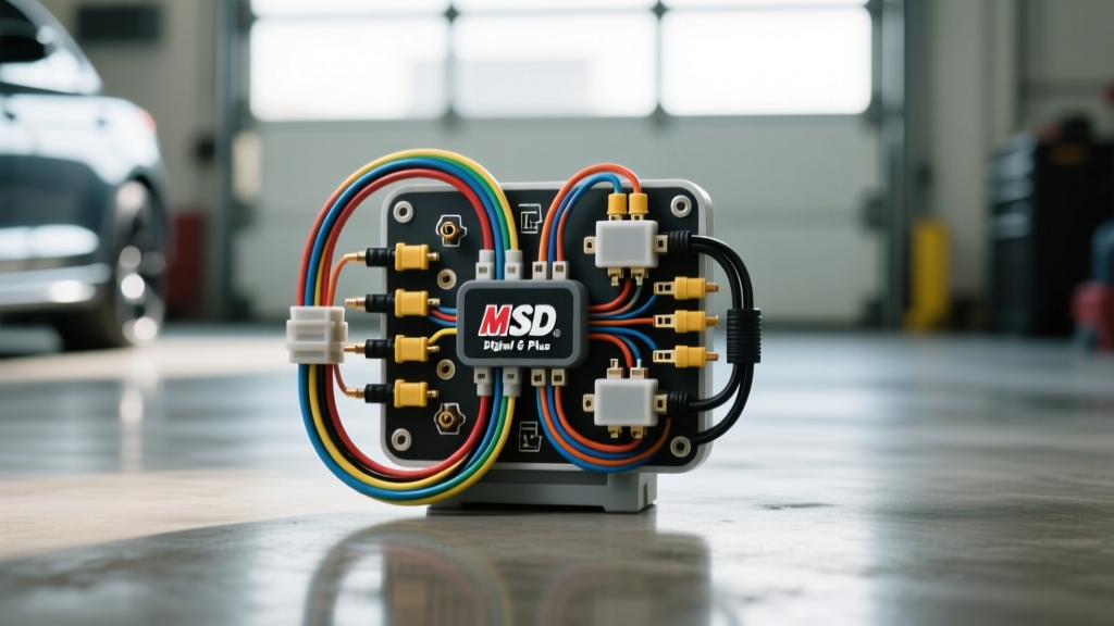
Introduction: The Stakes of High-Voltage CDI Wiring
The MSD Ignition Digital 6 Plus (Part Number 6281) is a cornerstone of high-performance ignition systems, delivering up to 150 millijoules of spark energy and multiple sparks up to 3,000 RPM. However, integrating this Capacitive Discharge Ignition (CDI) unit into a vehicle's electrical architecture requires strict adherence to the MSD wiring diagram Digital 6 Plus specifications. Unlike standard inductive ignition systems, the Digital 6 Plus utilizes an internal transformer to step up 12V DC to approximately 400-535V DC to charge its internal capacitors. A single wiring error—such as undersized ground wires, improper trigger polarity, or ignoring Electromagnetic Interference (EMI) routing—can result in catastrophic internal component failure, erratic engine timing, or severe electrical fires. This guide highlights the critical safety warnings and common installation mistakes that destroy these units, ensuring your ignition system operates at peak efficiency.
Critical Safety Warnings Before You Crimp
Working with CDI systems introduces hazards not present in standard automotive 12V circuits. Before cutting, stripping, or crimping any wires, review these mandatory safety protocols:
- Capacitor Discharge Hazard: The Digital 6 Plus stores lethal levels of electrical energy in its internal capacitors. Always disconnect the primary heavy red power wire and wait a minimum of five minutes before touching the ignition coil terminals or the Orange/Black output wires. A fully charged unit can deliver a severe shock even with the vehicle's battery disconnected.
- Ballast Resistor Bypass: Factory ignition systems (particularly older Chrysler/Mopar applications) utilize a 1.5-ohm ballast resistor or resistance wire to limit voltage to standard inductive coils. The MSD Digital 6 Plus requires a full, unregulated 12V+ supply during both 'Run' and 'Crank' cycles. Failing to bypass the factory ballast resistor will starve the CDI box, causing weak sparks and eventual internal transformer burnout.
- Ignition Coil Compatibility: Never use the Digital 6 Plus with an internally resisted 'HEI' style coil or an electronic distributor module. You must use a low-resistance ignition coil (typically 0.5 to 0.9 ohms primary resistance), such as the MSD Blaster 2 (PN 8202). Using a high-resistance coil will cause the CDI's output transistors to overheat and fail.
Decoding the MSD Wiring Diagram Digital 6 Plus
Understanding the specific gauge and routing requirements for each circuit is the difference between a reliable ignition system and a stranded vehicle. Below is a breakdown of the primary circuits.
Heavy Current Power and Ground Requirements
The most frequent cause of Digital 6 Plus failure is voltage drop on the primary power and ground circuits. The Heavy Red (12V+) and Heavy Black (Ground) wires draw massive instantaneous current—often exceeding 20 amps during high-RPM capacitor charging cycles.
- Wire Gauge: You must use a minimum of 10 AWG stranded copper wire for both the Heavy Red and Heavy Black circuits, though 8 AWG is highly recommended for runs exceeding 4 feet to the battery.
- Grounding Point: Never ground the Heavy Black wire to sheet metal, painted chassis components, or intake manifold bolts. It must be terminated directly to the engine block or the negative battery terminal. Use a serrated flange nut or a star washer under an M8 or M10 ring terminal, torqued to 18-22 lb-ft to bite through surface oxidation.
- Overcurrent Protection: Install a 30-Amp Maxi-Fuse or marine-grade circuit breaker on the Heavy Red wire, positioned within 6 inches of the battery positive terminal to protect the main power feed in the event of a short.
Trigger Wire Configurations and Polarity
The Digital 6 Plus supports multiple trigger sources, but misidentifying the trigger wires will result in a no-spark condition or a 180-degree timing error.
- Points / Amplifier Trigger: Uses the White wire. This wire requires a ground signal to trigger the CDI. When connecting to factory points or an electronic amplifier, ensure the White wire sees 12V when open, and drops to ground when closed.
- Magnetic Pickup Trigger: Uses the Violet (+) and Green (-) wires. These must be connected to the distributor's magnetic pickup stator. Swapping the Violet and Green wires reverses the polarity, which can cause the engine to backfire through the carburetor or run drastically retarded.
Top 5 Wiring Mistakes That Destroy Digital 6 Plus Units
- Using Standard Butt Connectors for Coil Wires: The Orange (Coil +) and Black (Coil -) wires carry high-frequency, high-voltage pulses. Standard vinyl butt connectors will melt or arc. Always use adhesive-lined heat shrink crimp terminals, and apply dielectric grease to the coil tower connections.
- Ignoring the Weep Hole: The MSD aluminum housing features a small weep hole designed to drain condensation. If the unit is mounted upside down or on its side where the weep hole faces upward, water will pool inside the potted circuitry, leading to inevitable short circuits.
- Splicing the Heavy Red Wire into Factory Ignition Switch Wiring: The factory ignition switch and bulkhead connectors cannot handle the 20+ amp draw of the CDI. The Heavy Red wire must be run directly to the battery (via a relay if switched power is desired for the activation circuit, though the Digital 6 Plus features an auto-start circuit that activates upon sensing engine rotation).
- Routing Trigger Wires Parallel to Spark Plug Wires: Running the White, Violet, or Green trigger wires alongside high-voltage spark plug wires induces EMI cross-talk. The CDI will interpret this EMI as a trigger signal, causing multiple erratic sparks and severe engine detonation.
- Improper 2-Step Rev Limiter Wiring: The Blue wire activates the 2-step module. Grounding this wire through a standard toggle switch without a relay can introduce resistance. If the ground path exceeds 0.5 ohms, the 2-step limit will engage and disengage erratically, destroying the transistors.
MSD Digital 6 Plus Pinout and Wire Color Reference Table
| Wire Color | Function | Recommended AWG | Connection / Routing Notes |
|---|---|---|---|
| Heavy Red | Main 12V+ Power | 8 - 10 AWG | Direct to Battery (+) via 30A Fuse |
| Heavy Black | Main Ground | 8 - 10 AWG | Engine Block or Battery (-), bare metal |
| Orange | Coil Positive (+) | 14 AWG (MSD Spec) | High dielectric insulation required |
| Black (Thin) | Coil Negative (-) | 14 AWG (MSD Spec) | Do not ground; connects only to coil (-) |
| White | Points / Amp Trigger | 18 AWG | Ground to trigger; keep away from EMI |
| Violet | Magnetic Pickup (+) | 18 AWG | Twist with Green wire to cancel noise |
| Green | Magnetic Pickup (-) | 18 AWG | Twist with Violet wire to cancel noise |
| Blue | 2-Step / Retard Activation | 18 AWG | Ground to activate; use relay for switches |
Routing, Ferrite Cores, and EMI Suppression
The Digital 6 Plus operates by rapidly switching high currents, which generates significant Electromagnetic Interference. To protect the vehicle's ECU, alternator diodes, and audio equipment, strict routing rules must be followed. According to SAE J1128 standards for low-tension primary cable, wire routing must account for thermal and electromagnetic degradation.
Always route the MSD harness on the opposite side of the engine bay from the spark plug wires. If crossing spark plug wires is unavoidable, do so at a strict 90-degree angle. Furthermore, if your vehicle utilizes a modern ECU or sensitive audio amplifiers, install a snap-on ferrite bead choke on the White trigger wire and the Heavy Red power wire, positioned within 3 inches of the CDI housing. This suppresses high-frequency RFI from traveling back into the vehicle's main wiring harness.
No-Spark Troubleshooting Decision Tree
If the engine cranks but produces no spark, follow this diagnostic sequence before condemning the CDI unit:
- Verify Primary Power: Using a digital multimeter, check voltage between the Heavy Red wire and the Heavy Black wire at the CDI connector during cranking. It must read above 10.5V. If it drops below 9V, inspect the main power feed and ground connections.
- Check Coil Resistance: Disconnect the Orange and Black wires from the ignition coil. Measure the primary resistance across the coil's positive and negative terminals. An MSD Blaster coil should read between 0.5 and 0.9 ohms. A reading of 'OL' (Open Loop) indicates a failed coil, not a failed CDI.
- Verify Trigger Signal: If using the White wire (points trigger), connect a test light between the White wire and 12V+. Crank the engine. The test light should flicker. If it remains solidly lit, the trigger is not grounding (faulty points or module). If it remains off, the White wire is shorted to ground.
- Perform the MSD Coil Spark Test: As detailed in the official Holley/MSD installation instructions, use the provided yellow testing wire to touch the White wire to ground repeatedly with the key in the 'Run' position. A strong blue spark from the coil wire to ground confirms the CDI and coil are functional, isolating the fault to the distributor trigger circuit.