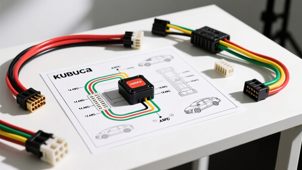
Demystifying the Kubota Ignition Switch Electrical Wiring Diagram PDF
For beginners and seasoned mechanics alike, tracking down an electrical gremlin in a compact tractor can feel overwhelming. When your engine fails to crank, or your dashboard lights remain dead, the ignition switch is the primary suspect. Locating the correct ignition switch electrical kubota wiring diagram pdf is your first step toward a successful diagnosis. Whether you are working on a B-series, L-series, or M-series Kubota tractor, the fundamental principles of the ignition harness remain remarkably consistent. This guide breaks down the schematic symbols, wire color codes, and pinout configurations you need to confidently test, repair, or upgrade your Kubota ignition system without relying on expensive dealership diagnostics.
How to Read Kubota Schematic Symbols
Before grabbing a multimeter, you must understand the visual language of the wiring diagram PDF. Kubota schematics use standardized symbols that represent physical components and wire routing.
- Nodes and Splices: A solid black dot where two lines intersect indicates a physical splice or solder joint. If lines cross without a dot, they are merely passing over one another without making electrical contact.
- Switch Contacts: The ignition switch is depicted as a series of sliding contacts. The diagram will show the switch in the 'OFF' position by default, with dotted lines indicating which pins bridge together when turned to 'ON', 'START', or 'GLOW'.
- Relays and Solenoids: Rectangles with internal coils represent relays. The starter solenoid is usually shown as a heavy-duty relay directly connected to the battery and starter motor.
- Ground Symbols: An inverted triangle or a series of decreasing horizontal lines indicates a chassis ground. In Kubota tractors, the engine block and main frame serve as the primary ground return path.
Standard 5-Pin Kubota Ignition Switch Pinout & Specifications
Most mid-range Kubota tractors utilize a 5-pin or 6-pin weather-pack connector plugged directly into the back of the ignition cylinder. Understanding the exact function and American Wire Gauge (AWG) requirements for each pin is critical for preventing voltage drop and harness fires. According to SAE J1128 standards for low-tension primary cables, wire gauge must be matched to the maximum amperage draw of the circuit.
| Pin Label | Function | Typical Kubota Wire Color | Recommended AWG | Destination / Load |
|---|---|---|---|---|
| B (Battery) | Main 12V Power Feed | Red | 10 AWG | Fusible Link / Main Harness Relay |
| IG (Ignition) | Switched 12V Power | White or White/Red | 14 AWG | Fuel Solenoid, Dash Gauges, ECU |
| ST (Start) | Starter Solenoid Trigger | Yellow/Red or Yellow | 12 AWG | Starter Solenoid 'S' Terminal |
| G (Glow) | Pre-heat / Glow Plugs | Black or Black/White | 10 AWG (Relayed) | Glow Plug Relay Coil or Timer |
| ACC (Accessory) | Switched Accessory Power | Blue or Green | 16 AWG | Radio, Work Lights, Beacon |
The 'Glow Plug Melt' Phenomenon: A Critical Wiring Warning
If you are studying a Kubota ignition switch electrical wiring diagram pdf for an older B-series or L-series tractor, you must be aware of a notorious factory design flaw. On many early models, the 'G' (Glow) pin routed the full amperage draw of the glow plugs (often 40 to 60 amps) directly through the ignition switch contacts and the tiny 14 AWG harness wires. The switch contacts are typically only rated for 15 amps continuous.
The Failure Mode: Over time, the resistance at the 'G' pin increases due to minor corrosion and thermal cycling. This resistance generates immense heat, literally melting the plastic weather-pack connector and fusing the ignition switch internals. If your tractor struggles to start when cold, or if you smell melting plastic near the dash, inspect the 'G' pin immediately.
The Expert Fix: Never simply replace the switch and connector with OEM parts and hope for the best. Use the wiring diagram to reroute the glow plug circuit through a heavy-duty 40A Bosch-style automotive relay. The ignition switch should only trigger the relay coil (drawing less than 1 amp), while the relay handles the heavy current directly from the battery via 8 AWG wire. Resources on TractorByNet feature extensive community-documented relay upgrade schematics for this exact issue.
Beginner Multimeter Testing: Continuity Mapping
You do not need an oscilloscope to diagnose a Kubota ignition switch. A basic digital multimeter (DMM) set to the continuity or resistance (Ohms) setting is all you need. Always disconnect the negative battery terminal before performing continuity tests to prevent short circuits.
- Isolate the Connector: Unplug the main harness connector from the back of the ignition switch. You will be testing the male pins on the switch itself.
- Test OFF Position: Place one probe on the 'B' pin and the other on 'IG'. The meter should read 'OL' (Open Loop). There should be zero continuity between any pins in the OFF position.
- Test ON Position: Turn the key to the first click (ON). Test 'B' to 'IG' and 'B' to 'ACC'. Both should show near-zero resistance (under 0.5 ohms). This confirms power is flowing to the dash and fuel solenoid.
- Test GLOW Position: Turn the key counter-clockwise to the GLOW position. Test 'B' to 'G'. You should see continuity. If the resistance fluctuates or reads high, the internal contacts are carbon-fouled and the switch must be replaced.
- Test START Position: Turn the key fully clockwise to START. Test 'B' to 'ST'. Continuity must be solid. Note that in most Kubota diagrams, the 'IG' circuit remains live during cranking to keep the fuel solenoid engaged.
Upgrading and Repairing Your Harness
When your wiring diagram PDF reveals a damaged wire or a melted connector, proper repair techniques are mandatory. Tractors operate in high-vibration, high-moisture environments. Standard electrical tape and twist-splices will fail rapidly, leading to intermittent stalling or no-start conditions.
Always use adhesive-lined marine-grade heat shrink terminals when splicing wires. The inner adhesive melts and seals the wire strands, preventing capillary action from drawing moisture into the copper strands—a phenomenon known as 'green rot' that causes severe voltage drop. When replacing the main ignition connector, source OEM-style weather-pack connectors with proper silicone weather seals. Ensure you use a dedicated ratcheting crimping tool designed for weather-pack terminals; a standard pair of pliers will not provide the gas-tight crimp required to survive engine bay vibrations.
For comprehensive, model-specific diagrams and torque specifications for electrical ground points, always refer to the official Kubota USA Technical Support portal or your specific model's Workshop Manual (WSM). Armed with the right PDF and a solid understanding of these fundamentals, you can conquer any Kubota ignition electrical fault with confidence.