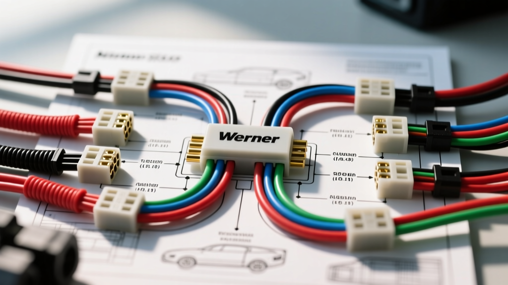
Introduction to Werner Sensor Applications in Heavy-Duty Vehicles
When dealing with commercial diesel trucks, custom RV builds, and heavy-duty marine applications, the Werner sensor wiring diagram is a critical reference for maintaining accurate pressure and temperature telemetry. Werner transducers are renowned for their robust construction and high-pressure tolerance, but like all automotive electrical components, they are susceptible to harness degradation, EMI (Electromagnetic Interference), and connector corrosion. Understanding the exact pinout, wire gauge requirements, and ratiometric signal behavior is essential for accurate diagnostics.
This guide provides a comprehensive, step-by-step troubleshooting flow for the standard 3-wire Werner pressure/temperature sensor. We will bypass generic guesswork and focus on precise multimeter testing, voltage drop analysis, and real-world failure modes that plague heavy-duty wiring harnesses.
Standard Werner Sensor Wiring Diagram & Pinout Configuration
Most Werner heavy-duty sensors utilize a 3-wire ratiometric configuration housed within a sealed Deutsch DT or Weather-Pack connector. The sensor requires a stable 5-volt reference from the ECU/PCM, a dedicated sensor ground, and a signal return wire. Below is the standard pinout and wiring specification chart.
| Pin Number | Function | Standard Wire Color | AWG Size | Wire Type |
|---|---|---|---|---|
| Pin 1 | 5V Reference (VREF) | Red | 18 AWG | TXL (Cross-linked) |
| Pin 2 | Signal Return (SIG) | Green | 18 AWG | TXL (Shielded) |
| Pin 3 | Sensor Ground (GND) | Black | 18 AWG | TXL (Cross-linked) |
Note: Always verify your specific Werner part number, as some high-temperature variants may use a 4-wire bridge configuration. The 3-wire ratiometric setup is the most common for standard fuel, oil, and boost pressure applications.
Step-by-Step Troubleshooting Flow
When a diagnostic trouble code (DTC) such as P0190 (Fuel Rail Pressure Sensor Circuit) or a generic heavy-duty SPN (Suspect Parameter Number) is triggered, follow this sequential decision tree to isolate the fault. Never replace the sensor before verifying the harness.
Step 1: Visual Inspection & Harness Integrity
- Disconnect the Battery: Isolate the negative terminal to prevent accidental ECU shorts during probing.
- Inspect the Deutsch DT Connector: Look for pushed-back pins, cracked wedgelocks, or missing secondary seals. Moisture ingress here is the #1 cause of erratic signal codes.
- Check for Chafing: Trace the harness 12 inches back from the sensor. Heavy-duty engines vibrate severely; look for the TXL wire insulation rubbing against the engine block or bracketry.
- Verify Crimp Integrity: According to IPC-A-620 Wire Harness Standards, a proper Deutsch solid-barrel crimp must show the wire flush with the inspection window. If you see 'birdcaging' or pulled strands, cut and re-crimp.
Step 2: 5V Reference Circuit Testing
- Reconnect Battery & Turn Key to ON (Engine OFF):
- Back-probe Pin 1 (Red Wire): Using a T-pin and a digital multimeter (DMM) set to DC Volts, probe the harness side of Pin 1. Connect the DMM black lead to a known good engine block ground.
- Analyze Reading:
- 4.9V - 5.1V: Circuit is healthy. Proceed to Step 3.
- 0.0V: Open circuit or ECU internal fault. Check for a blown 5V reference fuse in the power distribution center.
- 1.5V - 3.0V: The 5V reference is being pulled down. This usually indicates a short to ground in the harness, or another sensor sharing the same 5V VREF circuit has failed internally. Disconnect other sensors on the same VREF loop to isolate the short.
Step 3: Signal Return & Ground Circuit Verification
Do not rely on a simple continuity test for the ground circuit. A single strand of 18 AWG wire can pass a continuity beep test but still fail under load due to high resistance. You must perform a Voltage Drop Test.
- Ground Voltage Drop Test: Connect the DMM red lead to the battery negative terminal and the black lead to Pin 3 (Black wire) at the sensor connector. With the circuit active, the voltage drop should be less than 0.1V. Anything higher indicates corrosion or a loose ground eyelet at the chassis.
- Signal Sweep Test: Back-probe Pin 2 (Green wire).
- Key ON, Engine OFF (0 PSI): The signal should read approximately 0.5V.
- Engine Running (Under Load): As pressure increases, the voltage should climb linearly. At maximum rated pressure (e.g., 150 PSI for a typical fuel pressure Werner sensor), the signal should approach 4.5V.
- Identify EMI Interference: If the signal voltage fluctuates wildly (e.g., jumping from 1.2V to 3.8V instantly) without a corresponding change in physical pressure, the green signal wire has lost its shield grounding or is routed too close to high-current alternator cables. Refer to SAE J1939 Standards for proper heavy-duty CAN-bus and analog sensor routing separation.
Symptom-Cause-Fix Diagnostic Matrix
Use this quick-reference matrix to correlate your multimeter findings with the correct repair procedure.
| Symptom / DMM Reading | Probable Cause | Corrective Action |
|---|---|---|
| Signal reads exactly 4.9V - 5.0V at all times | Signal wire (Pin 2) shorted to 5V Reference (Pin 1) | Inspect harness for melted insulation between Red and Green wires. Repair or replace harness segment. |
| Signal reads 0.0V with Key ON | Signal wire shorted to ground, or internal sensor failure | Disconnect sensor. If harness reads 0V, repair harness short. If harness reads 0.5V, replace Werner sensor. |
| Erratic signal jumping >1V instantly | Electromagnetic Interference (EMI) or loose pin crimp | Reroute signal wire away from alternator/injector harnesses. Verify Deutsch wedgelock is fully seated. |
| 5V Reference reads 2.5V | VREF circuit overloaded by a failed secondary sensor | Isolate sensors sharing the VREF. Replace the component pulling the circuit to ground. |
Common Failure Modes and Real-World Fixes
The 'Phantom' Pressure Spike
A frequent complaint in custom diesel builds utilizing Werner sensors is a 'phantom' pressure spike on the datalogger, triggering limp mode. This is rarely a sensor failure. It is almost always caused by injector pulse EMI inducing a voltage spike in the unshielded signal wire. The Fix: Replace the standard 18 AWG green signal wire with a shielded 18 AWG cable. Ground the shield drain wire at the ECU end only (single-point grounding) to prevent ground loops, a best practice endorsed by leading automotive sensor manufacturers.
Connector Wedgelock Failure
In high-vibration environments (e.g., mounted directly to a vibrating fuel rail), the male and female pins inside the Deutsch connector can back out if the secondary wedgelock was not fully engaged during assembly. This causes intermittent open circuits that log as 'Signal Voltage High'. The Fix: Always use a dedicated Deutsch pin insertion tool. After inserting the crimped wire, pull back gently on the wire to ensure the retaining barb has caught. Insert the plastic wedgelock until it clicks flush with the connector housing.
Conclusion
Troubleshooting a Werner sensor wiring diagram requires moving beyond simple parts-swapping. By systematically verifying the 5V reference, performing voltage drop tests on the ground circuit, and analyzing the ratiometric signal sweep under load, you can accurately pinpoint whether the fault lies in the ECU, the TXL wiring harness, or the sensor itself. Always adhere to heavy-duty crimping standards and maintain strict separation between low-voltage analog signals and high-current power cables to ensure long-term reliability.