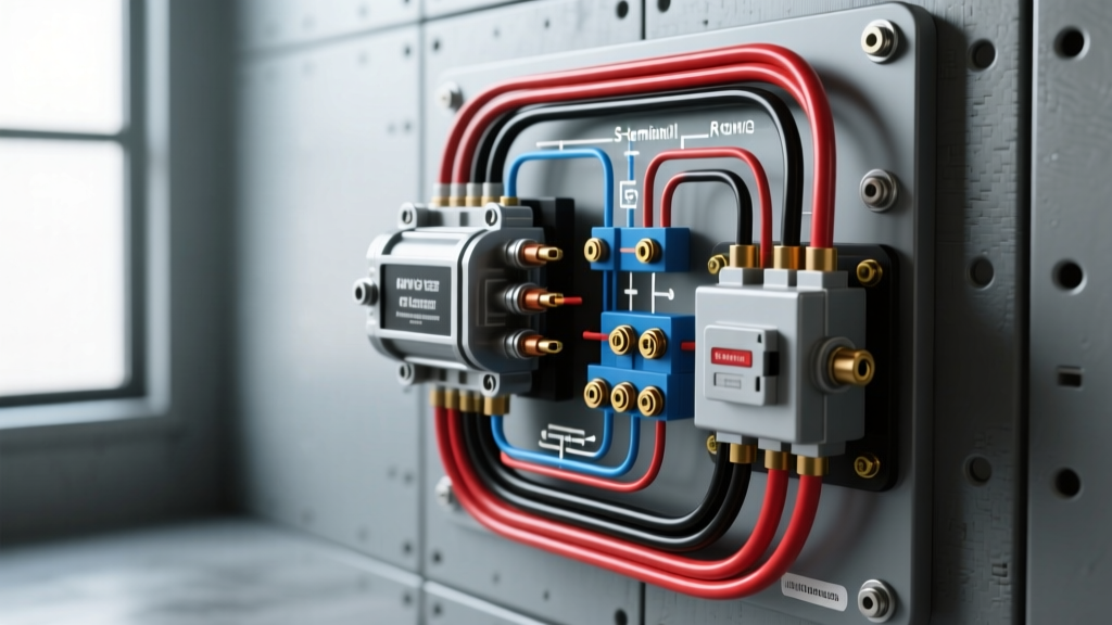
Decoding the Car Starter Wiring Diagram for High-Torque Upgrades
Upgrading from a heavy, direct-drive OEM starter to a gear-reduction mini starter is one of the most effective reliability modifications you can perform on a classic V8 engine. These high-torque units draw significantly different amperage profiles and require precise electrical routing to function reliably. Simply bolting on the new unit and reusing the degraded factory harness is a recipe for electrical failure, slow cranking, and solenoid burnout. To ensure maximum cranking torque and longevity, you must strictly follow an updated car starter wiring diagram tailored for high-amperage gear-reduction units.
In this practical installation guide, we will walk through the exact wiring protocols for upgrading a classic GM/Chevy V8 to a modern Denso-style gear-reduction mini starter. We will cover main battery cable AWG sizing, solenoid trigger circuit upgrades, and the critical 'R-terminal' ballast bypass that plagues so many first-time installers.
Required Materials and AWG Specifications
Before cutting any wires, gather the correct materials. Using Copper Clad Aluminum (CCA) wire instead of pure bare copper is a common mistake that leads to severe voltage drop under the massive inductive load of a starter motor. Always refer to the SAE J1128 Low Tension Primary Cable Standard for automotive wiring benchmarks.
| Circuit Function | Recommended AWG | Terminal Type | Max Allowable Voltage Drop |
|---|---|---|---|
| Main B+ Battery Feed | 1/0 AWG (Pure Copper) | 3/8" Ring Terminal (Adhesive Heat Shrink) | 0.5V total under load |
| Engine Block Ground | 1/0 AWG (Pure Copper) | 3/8" Ring Terminal | 0.2V across connection |
| S-Terminal Trigger (Ignition Switch) | 10 AWG (Stranded Copper) | 1/4" Spade / Push-On | 0.5V total under load |
| Solenoid Relay Control (If used) | 14 AWG | Standard Bosch Relay Pins | N/A (Low current signal) |
Step-by-Step Installation and Wiring Procedure
Phase 1: Mechanical Mounting and Grounding
A starter motor completes its circuit through the engine block. If the mechanical mating surface is compromised, the starter will attempt to ground through the wiring harness or throttle linkage, causing catastrophic heat damage.
- Surface Prep: Use a wire wheel to clean the bellhousing mating surface on both the engine block and the starter nose cone. Bare, unpainted metal is mandatory.
- Mounting Hardware: Use the provided knurled starter bolts. The knurling is designed to center the starter perfectly in the block dowel pin holes to prevent pinion gear binding.
- Torque Specifications: Torque the mounting bolts to 35 lb-ft. Do not exceed this, as you risk cracking the aluminum nose cone of the mini starter or stripping the cast-iron block threads.
- Dedicated Ground Cable: Run a secondary 1/0 AWG ground cable directly from the negative battery terminal to a clean, tapped bolt hole on the engine block near the starter. This ensures the high-torque motor has a dedicated return path.
Phase 2: Upgrading the Main B+ Feed
The factory OEM wiring often relies on 4 AWG or 6 AWG cables designed for older, lower-torque direct-drive starters. Modern gear-reduction starters can pull upwards of 150-200 amps under heavy load.
- Cable Selection: Use 1/0 AWG pure copper welding cable. It offers superior flexibility for routing around exhaust headers and oil pans compared to stiff THHN wire.
- Termination: Strip the cable and crimp a 3/8" closed-barrel ring terminal using a hydraulic or heavy-duty mechanical crimper. Never solder large-gauge starter cables. Solder can wick under the insulation and create a brittle point that snaps under engine vibration.
- Sealing: Slide adhesive-lined marine heat shrink over the crimp before attaching. Apply heat until the adhesive oozes from the edges, creating a waterproof seal against road salt and engine bay moisture.
- Connection Torque: Secure the B+ cable to the large stud on the mini starter. Torque the nut to 75-100 in-lbs. Warning: Over-tightening this nut will cause the copper stud to spin inside the solenoid housing, destroying the internal connections.
Phase 3: Routing the S-Terminal Trigger Circuit
The S-terminal (Start terminal) is the small spade connector that signals the solenoid to engage. On classic GM vehicles, this is typically a purple wire originating from the ignition switch's 'Start' position, routed through the firewall bulkhead connector and neutral safety switch.
The Voltage Drop Problem: After 40 years, the ignition switch contacts and firewall bulkhead connectors degrade. It is incredibly common to measure only 9V to 10V at the starter S-terminal when the key is turned. Modern mini-starter solenoids require a solid 11.5V+ to engage reliably. If voltage is low, the solenoid will chatter, arc internally, and weld itself shut, resulting in a starter that refuses to disengage.
The Relay Solution: To fix this, integrate a standard 30A Bosch-style relay into your car starter wiring diagram.
- Pin 86: Connect to the OEM purple trigger wire (provides the low-current signal).
- Pin 85: Connect to a clean chassis ground.
- Pin 30: Connect directly to the starter B+ terminal or battery positive (provides high-current source).
- Pin 87: Run a new 10 AWG wire directly to the starter S-terminal spade.
This configuration uses the weak OEM signal merely to 'wake up' the relay, while the relay delivers full battery voltage directly to the solenoid.
Phase 4: Solving the OEM 'R-Terminal' Ballast Bypass
This is where most DIY installations fail. Classic GM points-style ignition systems utilized a ballast resistor wire (typically a pink wire with a white stripe) to drop the voltage to the coil to ~7V during normal running, preventing the points from burning up. However, during cranking, the ignition switch cuts power to the coil. To compensate, the OEM starter featured an 'R' terminal that fed full 12V directly to the coil only while the starter was engaged.
The Modern Dilemma: Most aftermarket mini starters do not have an R-terminal. If you are still running a points ignition, your engine will fire as soon as you release the key from 'Start' to 'Run', but it will die immediately because the coil loses its 12V cranking bypass.
The Fix:
- If you have upgraded to HEI or EFI: You do not need the R-terminal. HEI and EFI systems require full 12V at all times and draw their own power from a dedicated 'Run' circuit. Simply tape off and secure the OEM R-terminal wire so it doesn't short against the engine block.
- If you are keeping Points Ignition: You must install an external ballast resistor bypass relay, or wire a 1N5400 diode inline to prevent back-feeding the ignition circuit when the engine is running. Alternatively, the cleanest fix is to upgrade to an electronic ignition conversion kit (like PerTronix) and eliminate the ballast wire entirely.
Post-Installation Diagnostic Decision Tree
Once the wiring is complete, perform a voltage drop test as outlined by AA1Car Starting System Diagnostics before declaring the job finished. Place your multimeter in DC Volts mode and test while an assistant cranks the engine.
Symptom: Slow Cranking or Heavy Clicking
- Check 1: Measure voltage drop across the main B+ cable (Red probe on battery post, black probe on starter B+ nut). If reading > 0.5V, your cable is undersized or poorly crimped.
- Check 2: Measure voltage drop across the ground circuit (Red probe on starter housing, black probe on battery negative post). If > 0.2V, clean the block mating surface and check your secondary ground cable.
Symptom: Starter Heat Soak (Fails to crank when engine is hot)
Exhaust headers radiate immense heat, increasing the electrical resistance of the copper windings inside the starter and causing the solenoid plunger to stick. According to Powermaster Engineering Tech Tips, heat soak is the number one killer of mini starters.
- Fix A: Install a form-fitting ceramic heat shield blanket over the starter body.
- Fix B: Ensure your S-terminal relay is installed. Heat soak increases resistance; a relay ensures maximum voltage overcomes that resistance to snap the solenoid shut.
- Fix C: Verify exhaust header clearance. There must be a minimum of 1/2" air gap between the exhaust tube and the starter solenoid housing.
Symptom: Starter Run-On (Fails to disengage when key is released)
- Check 1: Inspect the ignition switch for internal welding. If the switch is stuck in the 'Start' position, it will continue to feed the S-terminal.
- Check 2: Verify the S-terminal relay is not stuck closed due to arcing. Always use a relay with a built-in suppression diode or resistor to prevent contact welding.
- Check 3: Check pinion gear clearance. If the starter is shimmed too far away from the flexplate, the pinion gear may not fully retract into the nose cone after cranking, keeping it mechanically engaged with the ring gear.
Conclusion
A successful high-torque starter upgrade relies entirely on respecting the physics of high-amperage DC circuits. By abandoning degraded OEM wiring, utilizing proper 1/0 AWG pure copper feeds, integrating an S-terminal relay, and properly addressing the R-terminal ballast bypass, you ensure your V8 fires instantly, every single time. Always reference your specific vehicle's factory service manual alongside your aftermarket car starter wiring diagram to account for unique neutral safety switch or clutch interlock configurations.