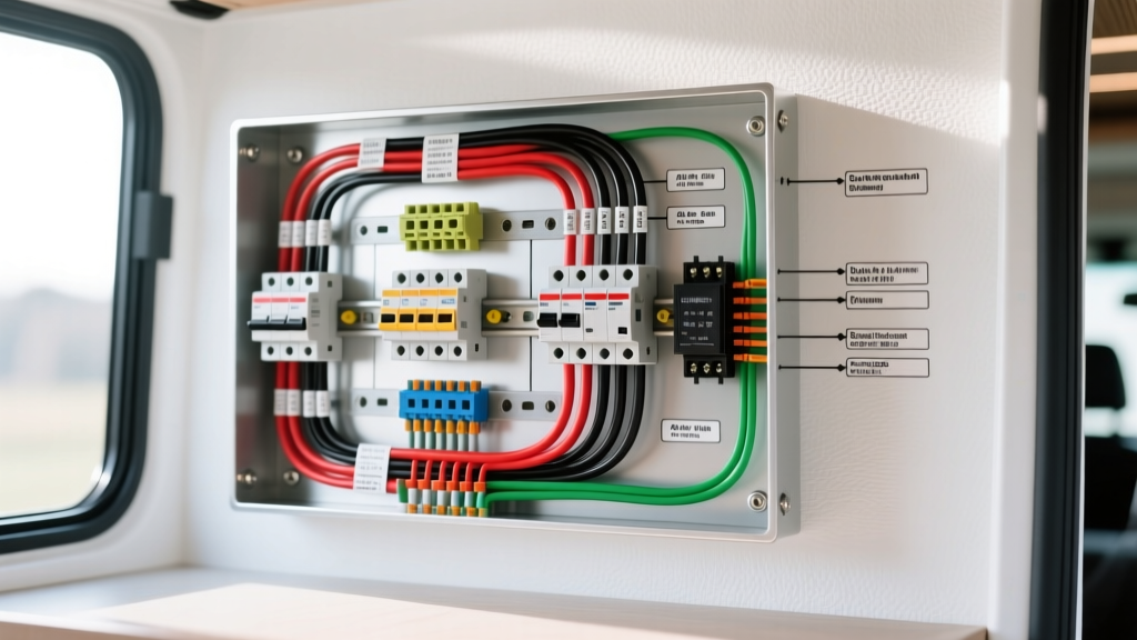
Architecting the 60A DC Subpanel for Van Conversions
When executing a comprehensive electrical upgrade on a Mercedes-Benz Sprinter (VS30) or Ford Transit, integrating a dedicated DC Power Distribution Unit (PDU) is critical for managing auxiliary house loads. In the context of automotive and overland upfits, a wiring diagram for 60 amp subpanel refers to the schematic governing a 60A auxiliary DC fuse block or terminal distribution block. This secondary panel isolates high-draw camper accessories from the vehicle’s OEM chassis harness, preventing parasitic drain on the starting battery and protecting sensitive CAN-bus systems from voltage spikes.
Defining the Automotive 60 Amp Subpanel
Unlike residential AC subpanels that step down voltage from a main breaker, an automotive 60A DC subpanel acts as a centralized branch-circuit protector. It receives a single 60A main feed from the auxiliary "house" battery bank (typically a 12V LiFePO4 or AGM setup) and distributes protected power to individual 12V loads such as compressor fridges, roof ventilation fans, water pumps, and LED lighting arrays. Adhering to ABYC E-11 AC & DC Electrical Systems standards—which are widely adopted by high-end RV and camper van builders—ensures your modification is both safe and compliant with mobile DC voltage drop requirements.
Wiring Diagram For 60 Amp Subpanel: Node-by-Node Schematic
Below is the logical flow schematic for a 12V nominal DC system utilizing a 60A subpanel. This architecture is specifically designed for Class B camper vans where space constraints demand efficient, high-current routing.
- Node A (Power Source): 12V LiFePO4 House Battery Bank (e.g., 200Ah capacity).
- Node B (Main Protection): 80A Class T Fuse on the positive battery terminal (sized to protect the main busbar wiring, allowing headroom for the 60A subpanel feed plus a 20A DC-DC charger bypass).
- Node C (Distribution Busbar): Positive and Negative copper busbars (M8 studs).
- Node D (Subpanel Feed): 6 AWG primary wire routed from the positive busbar to the 60A subpanel main input stud, protected by an inline 60A ANL or MRBF fuse.
- Node E (The 60A Subpanel): 12-Circuit ATC/ATO blade fuse block with integrated negative busbar and LED fault indicators.
- Node F (Branch Loads): Individual circuits (Fridge, Fan, Pump, Lights) routed to respective accessories.
- Node G (Grounding): All subpanel negative returns routed to the negative busbar, which is bonded to the vehicle chassis via a 2/0 AWG ground strap to prevent ground loops.
Wire Gauge, Routing, and Voltage Drop Specifications
Selecting the correct wire gauge is paramount in 12V DC systems. A mere 3% voltage drop can cause low-voltage disconnects (LVD) on sensitive electronics like the Dometic CFX3 compressor fridge. According to SAE J1128 standards for low-tension primary cable, you must use stranded copper wire with cross-linked polyethylene (XLPE) insulation, such as GXL or TXL, which withstands under-hood temperatures up to 125°C (257°F).
| Circuit Segment | Wire Gauge (AWG) | Max Continuous Load | Protection (Fuse) | Voltage Drop (per 10ft run) |
|---|---|---|---|---|
| Battery to Main Busbar | 2/0 AWG | 150A | 150A Class T | < 0.02V |
| Busbar to 60A Subpanel | 6 AWG | 60A | 60A ANL/MRBF | 0.20V (1.6%) |
| Subpanel to Compressor Fridge | 10 AWG | 15A (Inrush 25A) | 15A ATC | 0.15V (1.2%) |
| Subpanel to Maxxair Roof Fan | 14 AWG | 5A | 10A ATC | 0.10V (0.8%) |
| Subpanel to 12V Water Pump | 14 AWG | 7.5A | 10A ATC | 0.15V (1.2%) |
| Subpanel to LED Lighting | 16 AWG | 3A | 5A ATC | 0.08V (0.6%) |
Insulation and Conductor Standards
Never use standard THHN building wire for automotive modifications. THHN lacks the flexibility to withstand constant vehicular vibration and its nylon jacket degrades when exposed to automotive fluids and extreme heat cycles. Always specify SAE J1128 GXL wire. For routing through sheet metal bulkheads (such as the B-pillar in a Sprinter van), use split-loom corrugated tubing and rubber grommets to prevent insulation chafing, which is the leading cause of dead shorts in upfit projects.
Integration with OEM Alternators and DC-DC Chargers
A critical aspect of the 60A subpanel upgrade is how the house battery is replenished. Modern vehicles like the Mercedes-Benz Sprinter and Ram ProMaster utilize LIN-bus controlled "smart" alternators. These alternators vary their output voltage (often dropping to 12.4V or lower during deceleration to save fuel), which will severely damage or undercharge a standard 12V LiFePO4 battery bank if connected directly.
To resolve this, install a DC-DC charger (e.g., Victron Orion-Tr Smart 12/12-30) between the OEM starting battery and the house battery busbar. The DC-DC charger intercepts the LIN-bus voltage variations and outputs a stable 14.2V bulk/absorption charge profile. The 60A subpanel then draws exclusively from the stabilized house battery busbar, ensuring that branch circuits receive clean, consistent voltage regardless of the OEM alternator's current state of charge.
Troubleshooting Real-World Subpanel Failure Modes
Inductive Kickback and Nuisance Tripping
A common issue when wiring 12V compressor fridges or high-CFM ventilation fans to a 60A subpanel is nuisance fuse blowing. These accessories feature inductive electric motors. When the motor's internal relay opens, it generates a reverse voltage spike (inductive kickback) that can momentarily exceed the trip threshold of a standard fast-acting ATC blade fuse. The Fix: Use time-delay (slow-blow) fuses for inductive loads on the subpanel, or install a flyback diode across the motor terminals to suppress the voltage spike.
Ground Loop Interference in Sensor Wiring
If your subpanel powers a 12V water pump and a capacitive touch LED dimmer on the same ground busbar, you may experience flickering lights every time the pump cycles. This is a ground loop caused by voltage ripple on the shared negative return path. The Fix: Implement a "star grounding" topology. Instead of daisy-chaining the negative wires from the pump and the lights, route individual 14 AWG ground wires from each component directly back to the main negative busbar. Reference the Blue Sea Systems Technical Support guides on star grounding for marine and RV applications to eliminate electrical noise.
Termination and Torque Specifications
The reliability of your wiring diagram for 60 amp subpanel execution relies entirely on termination quality. Vibration will loosen poorly crimped connections, leading to increased resistance, localized heating, and potential fires.
- Crimping: Use a ratcheting hex-crimp tool for all lugs. Never use pliers. For 6 AWG and larger wires, use adhesive-lined dual-wall heat shrink (3:1 shrink ratio) to seal the crimp barrel against moisture and corrosion.
- Connectors: For accessories exposed to moisture (like the exterior water pump or solar roof glands), utilize Deutsch DT series connectors with silicone secondary locks and wedgelocks, rather than standard spade terminals.
- Torque Specs: When securing 6 AWG ring terminals to the subpanel's M6 input stud, apply exactly 4.5 to 5.5 Nm (40-48 in-lbs) of torque. For M8 busbar studs, torque to 10-12 Nm (88-106 in-lbs). Always use a split washer or Belleville disc washer under the nut to maintain clamping force during thermal expansion and contraction cycles.
By strictly following this wiring diagram for 60 amp subpanel architecture, your overland or camper van modification will yield a robust, fault-tolerant electrical system capable of handling the rigorous demands of off-grid mobile living.