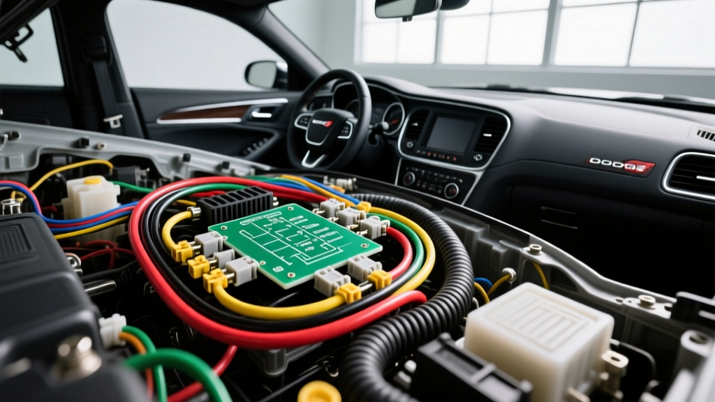
Introduction to the LX/LD Platform Electrical Architecture
Navigating the Dodge Charger wiring harness diagram requires a fundamental understanding of the Chrysler LX and LD platform electrical architecture. Unlike older vehicles that relied on point-to-point analog wiring, the modern Charger (specifically the 2011-2023 LD generation) utilizes a highly multiplexed network. This system distributes electrical loads across multiple modules, including the Powertrain Control Module (PCM), the Totally Integrated Power Module (TIPM), and the Body Control Module (BCM). When diagnosing a no-start condition, a lighting failure, or an aftermarket accessory integration issue, referencing the correct OEM wiring schematic is mandatory. This complete walkthrough dissects the primary harness routing, PCM pinouts, and common failure modes inherent to the Charger's electrical system.
Understanding the Totally Integrated Power Module (TIPM)
The TIPM is the central nervous system for the Charger's power distribution. Located in the front-left corner of the engine bay, it replaces the traditional under-hood fuse block and several standalone relays. The main power feed to the TIPM originates from the battery via a heavy-duty 4 AWG red cable terminating at the high-current stud. Inside the TIPM, this power is distributed through high-amperage cartridge fuses and internal printed circuit board (PCB) traces.
A critical failure mode in 2011-2014 Dodge Chargers involves the internal fuel pump relay. The solder joints on the TIPM PCB crack due to thermal cycling, resulting in an intermittent or complete loss of power to the fuel pump. According to Stellantis Tech Authority service bulletins, the OEM fix involves either replacing the entire TIPM unit or performing an external relay bypass harness installation, which taps into the 14 AWG Dark Green/Yellow wire at the TIPM C7 connector to supply direct power to the fuel pump module.
Dodge Charger Wiring Harness Diagram: PCM Pinout Walkthrough
The Powertrain Control Module (PCM) on the 5.7L and 6.4L HEMI V8 engines is mounted to the passenger side strut tower area. It features three primary connectors: C1 (Black, 38-way), C2 (Gray, 38-way), and C3 (Green, 38-way). When reading the Dodge Charger wiring harness diagram, it is vital to verify the connector cavity numbers, as they are stamped directly into the plastic housing.
PCM Connector C1 (Black) - Power, Ground, and Injector Control
| Cavity | Wire Color | AWG | Function / Description |
|---|---|---|---|
| 1 | Pink | 18 | Fused B+ (Ignition Off-Draw) |
| 12 | Black/Light Blue | 18 | Sensor Ground (Shared with MAP/TPS) |
| 29 | Dark Green/Orange | 18 | Injector 1 Control (PWM Driver) |
| 30 | Dark Green/Brown | 18 | Injector 2 Control (PWM Driver) |
| 35 | Black | 14 | Power Ground (Main PCM Chassis Ground) |
The injector control circuits utilize a saturated-switch pulse-width modulation (PWM) strategy. The PCM provides the ground path for the injectors. If you are probing these circuits with a logic probe or oscilloscope, expect to see a 12V baseline that drops to near 0V during the injector pulse event. The main power ground (Cavity 35, 14 AWG Black) routes directly to Ground Point G200 on the right strut tower. Corrosion at G200 is a frequent culprit for erratic PCM behavior and random misfire codes (P0300).
Engine Bay Sensor Wiring & AWG Specifications
Modern HEMI engines rely on precise sensor data to manage the Multi-Displacement System (MDS) and Variable Valve Timing (VVT). The wiring harness in the engine bay is wrapped in high-temperature corrugated loom and secured with friction tape to prevent abrasion against the aluminum intake manifold and exhaust heat shields.
Accelerator Pedal Position Sensor (APPS) Harness
The APPS is integrated into the throttle body assembly on the intake manifold. It utilizes a dual-redundant track design for safety. The harness consists of six wires:
- Pin 1: 5V Reference (Violet/White, 18 AWG)
- Pin 2: Signal 1 (Dark Blue/Dark Green, 18 AWG)
- Pin 3: Sensor Ground (Black/Light Blue, 18 AWG)
- Pin 4: 5V Reference (Violet/Gray, 18 AWG)
- Pin 5: Signal 2 (Dark Blue/Orange, 18 AWG)
- Pin 6: Sensor Ground (Black/Yellow, 18 AWG)
Because these are low-voltage analog signals, they are highly susceptible to Electromagnetic Interference (EMI). When repairing this section of the harness, never run the APPS wires parallel to the ignition coil power feeds. Always twist the 5V reference and ground wires together to maintain signal integrity.
Troubleshooting the CAN Bus Network (B-CAN and C-CAN)
The Dodge Charger utilizes a dual Controller Area Network (CAN) topology. The Chassis CAN (C-CAN) operates at 500 kbps and handles critical powertrain and ABS/ESP communications. The Body CAN (B-CAN) operates at 125 kbps and manages infotainment, HVAC, and interior lighting. Understanding the physical layer of these networks is crucial when using a Dodge Charger wiring harness diagram to diagnose communication faults (e.g., U0100 Lost Communication with ECM/PCM).
C-CAN Physical Layer Specifications
The C-CAN twisted pair originates from the PCM and loops through the ABS module, the Steering Column Lock Module (WCM), and the instrument cluster. The wires are distinctly color-coded:
- CAN High (C-CAN H): White/Light Green
- CAN Low (C-CAN L): White/Dark Green
According to SAE J1939 standards for high-speed CAN networks, the terminating resistors (120 ohms each) are located inside the PCM and the Instrument Cluster. When diagnosing a dead CAN bus, disconnect the battery and measure the resistance between CAN H and CAN L at the OBD-II diagnostic port (Pins 6 and 14). A healthy network will read exactly 60 ohms (two 120-ohm resistors in parallel). A reading of 120 ohms indicates an open circuit at one of the terminating modules, while a reading near 0 ohms indicates a short to ground or a short between the two CAN wires.
Headlight and Front Lighting Harness Routing
The front lighting harness on the Charger routes through the inner fender liners and connects to the headlamp assemblies via a sealed 10-way weather-pack connector. For models equipped with High-Intensity Discharge (HID) or factory LED headlights, the harness carries both low-current LIN (Local Interconnect Network) bus signals for the auto-leveling motors and high-current 14 AWG power feeds for the ballasts/drivers.
A common failure point is the ground ring terminal located behind the front bumper cover, designated as G104. Exposure to road salt and moisture causes galvanic corrosion between the copper wire and the steel chassis grounding point. When performing headlight harness repairs, always strip the wire using a precision wire stripper to avoid nicking the copper strands, crimp the terminal with a ratcheting crimper, and apply dielectric grease to the mating surfaces before torquing the grounding bolt to 10 Nm (88 in-lbs).
Splicing and Repair Best Practices
When modifying or repairing the Dodge Charger wiring harness, electrical tape and twist-on connectors are strictly prohibited. The OEM standard requires the use of cross-linked polyethylene (XLPE) insulated wire, which matches the high-temperature rating of the factory harness. For splicing, use adhesive-lined dual-wall heat shrink tubing with a brass crimp barrel. The adhesive lining melts during the shrinking process, creating a watertight seal that prevents capillary action from drawing moisture into the copper strands. For comprehensive wiring schematics and connector cavity views, technicians should consult the Haynes Automotive Repair Manuals or the official OEM service portal.