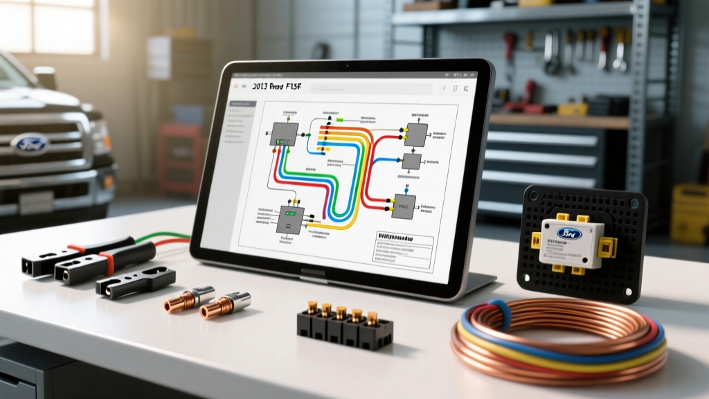
The Critical Role of the OEM Schematic in 12th-Gen F-150s
The 2013 Ford F-150 represents a highly integrated electrical architecture where the Body Control Module (BCM) and Smart Junction Box (SJB) manage everything from lighting to CAN-bus data networks. Unlike older generations where you could safely use a test light to find a 12V ignition source, probing the wrong wire in a 2013 model can fry a $600 BCM. This is why accessing and properly interpreting a 2013 Ford F150 wiring diagram PDF is non-negotiable for any aftermarket installation, whether you are wiring LED light bars, setting up upfitter switches, or installing a proportional trailer brake controller.
In this practical installation guide, we will break down how to read the factory schematics, identify the correct wire gauges, and execute military-spec splices for the most common 12th-generation F-150 upfit projects.
Decoding the 2013 Ford F150 Wiring Diagram PDF
Before cutting any wire, you must understand how Ford structures its electrical documentation. The OEM PDF is divided by system (e.g., Exterior Lighting, Power Distribution) and relies on a standardized alphanumeric grid.
Understanding Ford Circuit Numbering
Ford does not use arbitrary wire colors; they use standardized circuit numbers printed on the diagram. When you look at your 2013 F-150 schematic, you will see numbers inside circles next to the wire lines. Memorize these common circuits:
- Circuit 1001 (White/Red or Black): Constant Battery Positive (Hot at all times).
- Circuit 57 (Black): Chassis Ground.
- Circuit 10 (Light Green/Purple): Ignition Run/Start (Hot in RUN and START).
- Circuit 29 (White/Pink): Ignition Start Only (Hot only in START).
- Circuit 30 (Light Green/Yellow): Ignition Run Only (Hot in RUN, drops in START).
Navigating the SJB and BJB
The 2013 F-150 splits its fuses and relays between two main locations. The Battery Junction Box (BJB) is located in the engine bay and handles high-amperage circuits (starter, alternator, cooling fan, trailer tow). The Smart Junction Box (SJB) is located inside the cabin behind the right kick panel. The SJB contains solid-state relays and the BCM logic. Never tap directly into SJB output wires for high-draw accessories; always use the BJB or designated upfitter circuits.
Step-by-Step: Upfitter Switch Relay Installation
If your 2013 F-150 is equipped with the overhead console upfitter switches, the factory pre-runs four blunt-cut wires under the hood near the brake master cylinder. However, to use them safely, you must verify the circuit load against the diagram to prevent melting the harness.
| Switch | Relay Rating | OEM Wire Color | Ford Circuit # | Min. Wire Gauge (Extension) |
|---|---|---|---|---|
| AUX 1 | 30 Amp | Brown / White (BN/WH) | 1086 | 10 AWG |
| AUX 2 | 30 Amp | Brown / Light Green (BN/LG) | 1087 | 10 AWG |
| AUX 3 | 10 Amp | Violet / Orange (VT/OG) | 1088 | 14 AWG |
| AUX 4 | 10 Amp | Violet / Light Blue (VT/LB) | 1089 | 14 AWG |
Execution Steps for Upfitter Wiring
- Locate the Blunt-Cut Wires: Open the hood and look near the brake master cylinder on the driver's side firewall. You will find a bundle of 4 (or 6, if equipped with the snow plow prep package) wires taped up and capped.
- Verify with the Diagram: Cross-reference the wire colors with your 2013 Ford F150 wiring diagram PDF to ensure a previous owner hasn't modified the harness. Use a digital multimeter (DMM) to test for continuity to the BJB relay pins while an assistant toggles the overhead switches.
- Prepare the Extension Harness: Cut your 10 AWG or 14 AWG SAE J1128 cross-linked polyethylene (XLPE) wire to length. Strip exactly 3/8" of insulation using a precision wire stripper. Do not nick the copper strands, as this creates a stress riser that will snap under engine vibration.
- Crimp and Seal: Use an adhesive-lined marine-grade heat shrink butt connector (e.g., Ancor or Delphi). Crimp with a ratcheting crimper to ensure 4,000 PSI of compression. Apply heat starting from the center and moving outward until the adhesive oozes from the edges.
- Loom and Secure: Wrap the new extension in split-loom tubing and secure it to the factory harness using UV-resistant nylon cable ties every 8 inches. Keep the extension away from the exhaust manifolds and steering shaft U-joints.
Hardwiring a Trailer Brake Controller (C228 Connector)
The 2013 F-150 with the factory tow package includes a plug-and-play port under the dash for a brake controller. However, if you are doing a custom flush-mount install, or if the factory port is damaged, you must hardwire using the schematic for Connector C228.
C228 Brake Controller Pinout
- Pin 1 (Circuit 1001): Black wire - Constant 12V+ (Requires a 30A inline MAXI fuse at the BJB).
- Pin 2 (Circuit 57): White wire - Chassis Ground (Must be terminated to a clean, bare metal surface on the dash support beam).
- Pin 3 (Circuit 511): Light Blue / Red wire - Stoplight Switch Input (Triggers the controller when the brake pedal is depressed).
- Pin 4 (Circuit 28): Dark Blue wire - Output to Trailer Electric Brakes (Routes to the 7-way RV blade at the rear bumper).
Splicing and Torque Specifications
When terminating the 12V+ and Ground wires for a hardwired brake controller, you will likely use the BJB power distribution studs. According to Ford's Body Builder Layout Book, the B+ stud on the BJB requires a torque specification of 89 lb-in (10 Nm). The ground ring terminal to the chassis stud (G100) must be torqued to 18 lb-ft (25 Nm). Always apply a dab of dielectric grease over the terminal after tightening to prevent galvanic corrosion between the copper ring terminal and the steel chassis stud.
Diagnostic Troubleshooting Tree
When your aftermarket install fails, use this symptom-cause-fix decision tree derived directly from the 2013 F-150 electrical diagnostic manual.
Symptom: Upfitter Switch Clicks, but No Power at Accessory
- Cause A: Blown BJB Mini-fuse. Fix: Check Fuses 28 and 29 in the BJB. Replace with exact OEM Littelfuse replacements.
- Cause B: High resistance ground at the accessory. Fix: Measure voltage drop between the accessory casing and the negative battery terminal. A reading above 0.1V indicates a bad ground. Sand to bare metal and re-terminate.
Symptom: Trailer Brakes Lock Up When Headlights are Turned On
- Cause A: Short between Circuit 511 (Stoplight) and Circuit 14 (Tail Lights) at the rear 7-way connector. Fix: Inspect the rear bumper harness for chafing against the frame rail. Separate the wires and apply liquid electrical tape.
- Cause B: Corroded 7-Way RV Blade. Fix: The factory 7-way on the 2013 F-150 is prone to moisture ingress. Disassemble the plug, clean the pins with electrical contact cleaner, and pack the rear cavity with marine bearing grease.
Authoritative References
To ensure long-term reliability and safety, always cross-reference your installations with official engineering standards and manufacturer documentation:
- Ford Motor Company Fleet & Body Builder Guides: The definitive source for F-150 upfitter circuits, BJB torque specs, and CAN-bus topology. Available at https://www.fleet.ford.com/truckbbas.
- SAE International Standard J1128: Specifies the requirements for low-tension primary cable used in automotive electrical systems, including temperature ratings and copper stranding counts. Reference: https://www.sae.org/standards/content/j1128_202104/.
- Motorcraft Service Information: Provides access to the exact OEM wiring diagram PDFs, connector cavity views, and pinpoint diagnostic tests for the 2013 F-150 SJB and BCM. Reference: https://www.motorcraftservice.com/.
By strictly adhering to the 2013 Ford F150 wiring diagram PDF and utilizing proper aerospace-grade crimping techniques, you ensure that your truck's electrical system remains as reliable as its powertrain, whether you are towing 10,000 pounds or lighting up a job site at midnight.