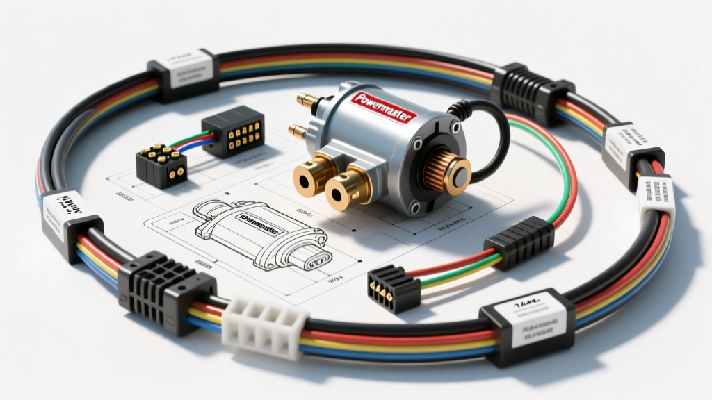
Upgrading to High-Torque: The Powermaster Starter Wiring Diagram
Swapping a heavy, heat-soaked OEM starter for a high-torque gear-reduction unit like a Powermaster 9000 or XS series is one of the most effective reliability upgrades for classic muscle cars, street rods, and performance trucks. However, installing the physical unit is only half the battle. A proper Powermaster starter wiring diagram execution is critical because these units can draw upwards of 250 to 300 amps of inrush current during initial engagement. If your wiring, crimps, or routing cannot handle this transient load, you will experience severe voltage drop, melted insulation, or solenoid failure.
This guide provides a comprehensive cost and tool requirements analysis for executing a professional-grade Powermaster starter wiring harness. We will break down the exact Bill of Materials (BOM), the specialized tooling required for heavy-gauge termination, and the electrical validation steps necessary to ensure your high-torque starter performs flawlessly.
Decoding the Powermaster Solenoid Pinout
Before purchasing materials, you must understand the terminal layout on the Powermaster solenoid. Most Powermaster gear-reduction starters utilize a 3-post or 4-post solenoid configuration. According to Powermaster Performance technical documentation, the standard pinouts are as follows:
- BAT (B+): The main battery feed stud. Typically 3/8-inch or 5/16-inch. This requires your heaviest gauge cable (1/0 AWG or 2 AWG).
- S (Start/Ignition): The trigger terminal. Receives 12V from the ignition switch's 'Start' position or a starter relay. Usually a 1/4-inch male spade. Requires 10 AWG or 12 AWG wire.
- R (Relay/Ballast Bypass): Provides a 12V bypass feed to the ignition coil during cranking, bypassing the factory ballast resistor. Only used on points-style or early electronic ignitions. 1/4-inch male spade.
- M (Motor): Connects to the starter motor. On most modern Powermaster units, this is an internal connection or a heavy braided strap pre-assembled at the factory. Do not wire external power here.
Essential Tool Requirements & Investment
Working with 1/0 AWG and 2 AWG battery cable requires more than a pair of standard pliers. Improper crimping on high-amperage circuits introduces micro-gaps that increase electrical resistance, leading to localized heating and eventual terminal failure. As noted in the wiring guides by Madelectrical.com, a hammer-and-punch crimp is entirely unacceptable for starter circuits.
Tooling Checklist and Estimated Costs
| Tool | Purpose | Estimated Cost | Pro-Tip |
|---|---|---|---|
| Hydraulic Wire Crimper (16-Ton) | Compression crimping 1/0 to 4 AWG ring terminals. | $80 - $140 | Use hex-shaped dies for a uniform, gas-tight crimp that won't slip under heat shrink. |
| Heavy-Duty Ratcheting Crimper | Crimping 8 to 16 AWG trigger and relay wires. | $35 - $50 | Ensure the ratchet releases only when the full crimp cycle is complete. |
| Heat Gun or Micro Torch | Shrinking adhesive-lined heat shrink tubing. | $25 - $45 | A micro torch provides better maneuverability in tight engine bays than a bulky heat gun. |
| Heavy-Gauge Wire Stripper | Stripping 1/0 and 2 AWG cable without nicking copper strands. | $30 - $60 | Nicking strands reduces the cross-sectional area and creates a weak point for voltage drop. |
| Digital Multimeter (True RMS) | Performing voltage drop tests under cranking load. | $50 - $300 | Must be capable of holding minimum/maximum readings to catch transient voltage drops. |
Total Tool Investment: $220 - $595 (depending on existing shop equipment).
Material Cost Breakdown: Wire, Terminals, and Protection
The materials you select dictate the longevity of your starter wiring. Standard copper-clad aluminum (CCA) wire or cheap vinyl insulation will degrade rapidly in the high-heat environment near the engine block and exhaust headers. You must use pure, tinned marine-grade copper wire that meets SAE J1128 or UL 1426 specifications.
Bill of Materials (BOM) for Powermaster Starter Harness
| Component | Specification | Est. Cost |
|---|---|---|
| Positive Battery Cable | 1/0 AWG Tinned Marine Copper (15 ft) | $65.00 |
| Negative Ground Cable | 1/0 AWG Tinned Marine Copper (6 ft) | $28.00 |
| Ignition Trigger Wire | 10 AWG Cross-Linked (GXL/TXL) (10 ft) | $12.00 |
| Ring Terminals (Main) | 1/0 AWG, 3/8" stud, adhesive-lined heat shrink | $18.00 (pack) |
| Spade/Ring Terminals (Trigger) | 12-10 AWG, 1/4" spade / #10 ring, nylon insulated | $10.00 (pack) |
| ANL Fuse & Holder | 200 Amp ANL Fuse with inline holder | $35.00 |
| Dual-Wall Heat Shrink | 3/4" and 1/2" adhesive-lined polyolefin | $22.00 |
| Dielectric Grease & Cleaner | Terminal cleaner brush and silicone grease | $15.00 |
Total Material Investment: ~$205.00
Step-by-Step Wiring Execution & Torque Specs
With your tools and materials acquired, the execution phase requires strict adherence to mechanical and electrical best practices.
1. Preparing and Crimping 1/0 AWG Cable
Strip exactly 7/8-inch of insulation from the 1/0 AWG cable. Slide a piece of 3/4-inch adhesive-lined heat shrink onto the wire before inserting the ring terminal. Insert the bare copper into the terminal barrel until it bottoms out. Using your hydraulic crimper with the correct hex die, apply pressure until the dies close completely. The adhesive inside the heat shrink will melt and seal out moisture and corrosive battery gases when heated.
2. Routing and Fusing the Main Feed
Route the 1/0 AWG positive cable from the battery to the Powermaster BAT stud. Never route the main starter cable without overcurrent protection. Install the 200A ANL fuse holder within 12 inches of the battery positive terminal. Keep the cable away from exhaust manifolds; if routing near heat sources is unavoidable, use fiberglass fire-sleeve wrapping.
3. Establishing the Ground Path
A Powermaster starter relies on the engine block for its ground return. Run a 1/0 AWG negative cable from the battery negative terminal directly to a clean, bare-metal mounting point on the engine block or cylinder head. Do not rely on the engine-to-chassis ground strap alone to carry 300 amps of starter current.
4. Torque Specifications
Overtightening the solenoid BAT stud can strip the threads or crack the phenolic insulator, causing a dead short to the starter casing. Use a calibrated inch-pound torque wrench.
- Solenoid BAT Stud Nut (3/8"): 85 - 105 in-lbs (approx. 7 - 9 ft-lbs).
- Engine Block Ground Bolt (5/16"): 15 - 20 ft-lbs.
- Battery Terminal Clamps: 50 - 70 in-lbs.
Troubleshooting: Voltage Drop Testing Under Load
The true test of your Powermaster starter wiring diagram is the voltage drop test. A visual inspection cannot reveal a poor crimp or internal wire strand corrosion. You must test the circuit while the starter is actively cranking the engine.
Performing the Positive Side Drop Test
- Set your Digital Multimeter to DC Volts.
- Place the red probe on the battery positive post (not the clamp, the actual lead post).
- Place the black probe directly on the Powermaster solenoid BAT stud.
- Crank the engine and observe the maximum voltage reading.
- Acceptable Limit: 0.5 Volts or less. If you read 0.8V or higher, you have excessive resistance in the positive cable, a failing ANL fuse connection, or a bad crimp.
Performing the Negative Side Drop Test
- Place the red probe on the battery negative post.
- Place the black probe on the starter motor housing (the bare aluminum case of the Powermaster unit).
- Crank the engine.
- Acceptable Limit: 0.2 Volts or less. A reading higher than 0.2V indicates a poor engine block ground, a corroded engine-to-chassis strap, or paint/dirt interfering with the starter mounting flange.
Conclusion: The Value of Doing It Right
Investing roughly $400 to $800 in combined tools and premium materials for your Powermaster starter wiring diagram ensures that your high-torque starter receives the full electrical potential it requires. By utilizing 1/0 AWG tinned copper, hydraulic hex crimps, adhesive-lined heat shrink, and validating the system with a voltage drop test, you eliminate the common failure points that plague budget wiring jobs. The result is an engine that fires instantly, regardless of ambient temperature or header heat soak, backed by a professional-grade electrical foundation.