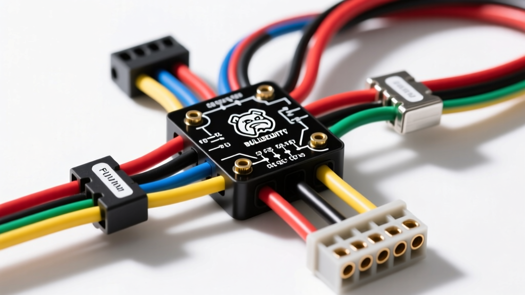
Understanding Your Bulldog Security Wiring Diagrams
Installing an aftermarket automotive security system can feel like deciphering an alien language, but Bulldog security wiring diagrams are actually designed with logical, standardized color codes. For beginners, the sheer volume of wires in the main harness and auxiliary relay packs can be overwhelming. However, by breaking the diagram down into functional circuits—power, ground, ignition, and triggers—you can confidently wire your vehicle without causing electrical gremlins or parasitic battery drains.
This beginner-friendly guide translates standard Bulldog security schematics into actionable steps. We will cover how to properly identify your vehicle's OEM wires, how to execute a safe starter interrupt, and how to avoid the most common installation mistakes that lead to blown fuses and damaged Electronic Control Units (ECUs).
Essential Tools and Safety Fundamentals
Before cutting a single wire, you must understand that modern vehicles utilize multiplexed data buses (like CAN-bus) and sensitive low-voltage sensors. Guessing wire functions by color is a guaranteed way to fry a Body Control Module (BCM). Always verify circuits with a Digital Multimeter (DMM) or a high-impedance logic probe.
- Digital Multimeter (DMM): Set to DC Voltage (20V scale) to test for 12V constants, ignition, and starter wires. Use the Ohms/Continuity setting to verify grounds.
- Wire Strippers and Crimpers: Use precision strippers to avoid nicking the copper strands, which reduces the wire's ampacity and violates SAE J1128 standards for automotive primary cable.
- Solder and Adhesive Heat Shrink: Avoid 'scotch locks' or T-taps. They cause voltage drop, invite corrosion, and can sever the OEM wire over time due to vibration. Always use a Western Union splice, rosin-core solder, and dual-wall adhesive heat shrink.
The Main Power Harness: Pinout and Color Codes
The primary harness on a Bulldog security module typically features a heavy-duty 12-pin or 6-pin connector responsible for powering the brain of the system and reading the vehicle's ignition states. Below is the standard translation of the Bulldog main power wiring diagram.
| Wire Color | AWG Size | Function | Connection Point & Testing Method |
|---|---|---|---|
| Red | 12 AWG | 12V Constant Battery | Connect directly to the battery positive or a main 12V constant feed. Must read 12.6V with the key OFF. |
| Black | 12 AWG | Chassis Ground | Bolt to bare, unpainted metal on the chassis. Do NOT ground to factory wire harness grounds. Must read 0.0 Ohms to battery negative. |
| Yellow | 18 AWG | Ignition 1 (Primary) | Shows 12V when the key is in the 'ON' and 'CRANK' positions. Drops to 0V when OFF. |
| Orange | 18 AWG | Accessory | Shows 12V in the 'ON' position, but drops to 0V during 'CRANK' to save battery for the starter. |
| Pink | 18 AWG | Starter | Shows 12V ONLY when the key is held in the 'CRANK' position. |
| Green | 18 AWG | Door Trigger (Negative) | Connects to the OEM dome light wire. Reads 12V when doors are closed, drops to 0V (ground) when opened. |
Note: Always fuse the Red 12V constant wire within 6 inches of the power source using an inline ATC fuse holder (typically 15A or 20A, depending on the specific Bulldog module's draw and siren output).
Wiring the Starter Interrupt Relay (Kill Switch)
The most critical security feature in your Bulldog diagram is the starter interrupt. This prevents the vehicle from cranking if the system is armed. Most Bulldog kits include a heavy-duty 40A automotive relay (often a standard ISO mini relay) for this purpose.
Understanding the ISO Relay Pins
Looking at the bottom of the relay, you will see five pins. Here is how they map to your Bulldog wiring diagram:
- Pin 30 (Common): Connects to the OEM starter wire going TOWARD the starter motor.
- Pin 87a (Normally Closed): Connects to the OEM starter wire coming FROM the ignition switch. When the alarm is disarmed, power flows from 87a to 30, allowing the car to start.
- Pin 87 (Normally Open): Not used for a standard starter kill. Tape it off.
- Pin 85 (Coil Ground): Connect to a solid chassis ground.
- Pin 86 (Coil 12V+): Connects to the Bulldog module's Starter Kill Output wire (often Blue/White or Light Green/Black, depending on the exact unit). When armed, the module sends a 12V signal here, energizing the coil and breaking the connection between 87a and 30.
Step-by-Step Starter Wire Cutting
- Locate the OEM starter wire at the ignition switch harness (usually a thick 10 AWG or 12 AWG wire, often Yellow or Purple, but always test with a DMM).
- Verify the wire: It should read 0V at rest, and jump to ~10.5V-12V only when the key is turned to 'CRANK'.
- Cut the OEM wire cleanly.
- Strip 1/2 inch of insulation from both cut ends.
- Solder the 'Key Side' to Relay Pin 87a, and the 'Starter Motor Side' to Relay Pin 30.
Decoding Door Triggers and Locks
Beginners often struggle with door triggers because vehicles use either negative or positive switching. The Crutchfield security installation guide emphasizes the importance of matching the trigger type to avoid back-feeding voltage into the BCM.
- Negative Trigger (Most Common): The OEM switch provides a ground path when the door opens. Use the Green wire on the Bulldog harness.
- Positive Trigger (Common in older Fords/Chryslers): The OEM switch sends +12V to the dome light when the door opens. Use the Blue wire on the Bulldog harness.
Pro-Tip: If your vehicle has a diode-isolated door trigger system (where each door has its own wire at the BCM), you must use 1A 1N4004 diodes to combine the signals into a single negative trigger for the Bulldog module. Point the diode stripe (cathode) toward the Bulldog module to prevent cross-triggering the dome lights.
Real-World Troubleshooting: What Went Wrong?
Even with perfect diagram interpretation, physical installation variables can cause issues. Use this decision tree to diagnose common beginner mistakes.
Symptom: The Siren Chirps, but the Starter Won't Crank (Even when Disarmed)
- Cause 1: The starter interrupt relay was wired backward. (Pin 30 and 87a swapped). Fix: Verify continuity between the ignition switch side and Pin 87a.
- Cause 2: The module thinks the vehicle is in 'Valet Mode' or the hood pin switch is engaged. Fix: Check the hood pin wire (usually Gray). If it reads ground, the system will disable the starter. Ensure the hood pin is fully extended and making contact only when the hood is open.
Symptom: The Alarm Randomly Triggers at Night
- Cause 1: Voltage drop on the door trigger wire causing the module to read a 'door open' state. Fix: Check your ground connections. A poor chassis ground will cause the module to seek ground through the door trigger circuit.
- Cause 2: Shock sensor sensitivity is too high, picking up heavy trucks driving by or wind. Fix: Turn the sensitivity dial on the shock sensor counter-clockwise to reduce the threshold.
Symptom: Parasitic Battery Draw (Car Won't Start After 3 Days)
Aftermarket security systems should draw less than 15mA in sleep mode. If you measure a draw of 200mA+ with your DMM in series with the battery negative terminal, you have a wiring fault. According to MECP (Mobile Electronics Certified Professional) standards, the most common cause is back-feeding power through the LED status indicator or an incorrectly wired trunk/hatch trigger. Ensure all unused trigger wires are capped and not touching bare metal, and verify that your relay coils are not remaining energized due to a shorted output transistor in the module.
Final Verification Before Reassembly
Before zip-tying the harness and reinstalling the lower dash panels, perform the 'Bulldog 5-Point Test':
- Arm the system and verify the siren chirps and parking lights flash.
- Attempt to crank the engine. It must NOT crank.
- Disarm the system, turn the key to ON, and verify all dash warning lights illuminate normally.
- Start the engine and verify it cranks and runs smoothly without stalling (ensures the ignition and accessory wires are correctly mapped).
- Open the door while armed to verify the siren triggers the full 30-second alarm cycle.
By respecting the Bulldog security wiring diagrams and adhering to proper automotive electrical standards, you ensure a reliable, factory-quality security installation that protects the vehicle without compromising its complex electrical architecture.