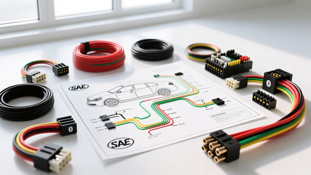
The Rosetta Stone of Automotive Diagnostics: Understanding the Wiring Diagram Legend
Every automotive technician and advanced DIYer knows that a complex wiring schematic without its corresponding legend is essentially an unreadable foreign language. The wiring diagram legend serves as the cryptographic key to decoding the intricate electrical networks of modern vehicles. Whether you are tracing a parasitic draw, diagnosing a multiplexed network fault, or installing an aftermarket accessory, mastering the legend is non-negotiable. According to the SAE J1292 Standard for automotive electrical and electronic systems, standardization of symbols and color codes is critical for cross-platform diagnostic accuracy.
This technical specification reference will break down the core components of an automotive wiring diagram legend, including SAE standardized symbols, OEM-specific wire color abbreviations, AWG-to-metric conversions, and connector nomenclature. We will also explore how to apply these legend elements to real-world diagnostic scenarios, ensuring you can navigate Motor Information Systems or OEM service manuals with absolute precision.
Standard SAE Symbol Classifications and Diagnostic Relevance
The legend at the bottom or side of a schematic defines the graphical symbols used to represent physical components. While basic symbols like batteries and resistors are universally understood, advanced diagnostic symbols require careful interpretation to avoid misdiagnosis.
| Symbol Name | Visual Representation | Diagnostic Relevance & Failure Modes |
|---|---|---|
| Chassis Ground | Line ending in three descending horizontal bars | Indicates a physical bolt to the vehicle frame. High resistance here (due to galvanic corrosion) causes erratic sensor readings and module resets. |
| Signal Ground | Line ending in a single horizontal bar with an arrow | Reference ground for 5V sensors (e.g., MAP, TPS). Must be measured against the battery negative terminal; voltage drop >0.05V indicates a faulty ECM ground circuit. |
| Shielded Wire | Dashed line enclosing the primary wire line | Used for high-frequency signals (CKP, CMP, Knock Sensors). The shield must be grounded at ONE end only to prevent ground loops and EMI interference. |
| Splice (S-Node) | Solid black dot where two or more lines intersect | Indicates a physical solder joint or crimp barrel inside the harness. A common failure point for green death (copper oxidation) if harness tape is compromised. |
| Normally Open (N.O.) Switch | Gap in the line with a hinged lever | Used for brake light switches and A/C pressure sensors. Contacts close upon mechanical or hydraulic actuation. |
| ISO Mini Relay | Rectangle with pins 30, 85, 86, 87, 87a | Pin 85/86 control the coil (check for 70-120 ohms). Pin 30 is B+ feed, 87 is N.O. output. Burnt contacts on 30/87 cause high-amp accessory failures. |
Decoding Wire Color Codes and Tracer Stripes
Wire color codes are heavily abbreviated in legends to fit within the narrow constraints of schematic lines. While GM Upfitter Body Builder Manuals and Ford service documentation share similarities, tracer stripes (secondary colors) and base colors vary. A wire labeled DK GRN/WHT indicates a Dark Green base wire with a White tracer stripe. The base color always dictates the primary circuit function, while the tracer denotes the specific branch or module destination.
Common OEM Wire Color Abbreviations
- BLK: Black (Typically primary ground or high-current B+ feeds)
- RED: Red (Switched or constant 12V B+ power)
- LT BLU: Light Blue (Often used for illumination or low-current signals)
- DK GRN: Dark Green (Frequently used for CAN High or sensor signals)
- YEL: Yellow (Often airbag/SRS circuits or ABS module feeds)
- WHT: White (Data lines, serial communications, or CAN Low)
- ORG: Orange (Battery positive feeds, often fused directly at the PDC)
- PPL / VIO: Purple / Violet (Injector control circuits or ignition triggers)
Wire Gauge: AWG vs. Metric Cross-Section
Modern legends, especially those for European and late-model domestic vehicles, frequently use metric cross-sectional area (mm²) instead of American Wire Gauge (AWG). Misinterpreting these can lead to catastrophic voltage drops or melted harnesses during repairs. The legend will usually specify the gauge next to the wire color (e.g., 18 GA or 0.8 mm²).
| AWG Rating | Metric Equiv (mm²) | Max Ampacity (Chassis Wiring) | Typical Automotive Application |
|---|---|---|---|
| 22 AWG | 0.35 mm² | 3 - 5 Amps | Low-current sensor signals, LIN bus, LED illumination. |
| 20 AWG | 0.50 mm² | 5 - 7 Amps | O2 sensor heaters, CAN bus networks, injector pulses. |
| 18 AWG | 0.80 mm² | 7 - 10 Amps | Relay coils, interior lighting, power window switches. |
| 16 AWG | 1.00 mm² | 10 - 13 Amps | Fuel pump feeds, horn circuits, blower motor relays. |
| 14 AWG | 2.00 mm² | 15 - 20 Amps | Headlight feeds, ABS pump power, accessory outlets. |
| 12 AWG | 3.00 mm² | 20 - 25 Amps | Main ignition feeds, high-amperage cooling fan circuits. |
| 10 AWG | 5.00 mm² | 30 - 40 Amps | Alternator B+ output, starter solenoid feeds, PTC heaters. |
Connector and Pinout Nomenclature
The legend provides the key to understanding alphanumeric connector designations. Most OEMs use a standardized grid system to identify harness-to-harness or harness-to-component connections.
Connector Prefixes (OEM Standardized)
- C100 - C199: Engine compartment harness connectors (e.g., C101 is typically the main engine-to-dash bulkhead connector).
- C200 - C299: Instrument panel and dash harness connectors.
- C300 - C399: Body and chassis harness connectors (e.g., C305 often routes to the rear taillight harness).
- C400 - C499: Door and mirror harness connectors.
Pin Cavity Numbering: The legend will specify that cavities are numbered looking into the mating face of the connector. Pin 1 is usually denoted by a raised triangle or a distinct colored cavity plug. When a schematic reads C205 Pin 14 (18 AWG RED/WHT), you must locate the C205 connector, find cavity 14, and verify the physical wire matches the 18-gauge Red with White tracer specification. If the wire is Black, a previous technician has miswired the harness or performed a sloppy splice repair.
Ground Distribution and Splice Pack References
Grounds and splices are the most common failure points in automotive electrical systems. The legend defines the naming conventions for these hidden nodes.
- G100 - G199: Engine block and cylinder head grounds. (e.g., G103 is the main ECM ground on the rear of the block).
- G200 - G299: Instrument panel and dash grounds. Often tied to the steering column support bracket.
- G300 - G399: Body and chassis grounds. Frequently located in the kick panels or rear cargo area.
- S100 - S199: Engine harness splices. S104 is often the injector power feed splice pack.
- S200 - S299: Dash harness splices. S204 is a notorious failure point for CAN bus communication faults in many domestic vehicles.
Advanced Legend Elements: Multiplexed Networks and Shielding
Modern vehicles rely heavily on Controller Area Network (CAN), Local Interconnect Network (LIN), and FlexRay buses. The wiring diagram legend will feature specific symbols for these networks. A twisted pair symbol (two intertwining lines) indicates a differential signal pair. The legend will also specify the drain wire (usually an uninsulated bare copper or silver wire) that must be grounded to the shield of the connector to prevent electromagnetic interference (EMI) from corrupting the high-speed data.
For LIN bus circuits, the legend will denote a single-wire multiplexed line, typically 20 AWG or 22 AWG, pulling up to 12V via an internal module resistor. If the legend shows a LIN bus line routing to a smart alternator or a steering wheel control module, do not probe it with a standard test light, as the high current draw will fry the LIN transceiver inside the control module. Always use a high-impedance digital multimeter (DMM) or an oscilloscope.
Troubleshooting Application: Tracing a CAN Bus Fault
Let us apply the legend to a real-world scenario: A vehicle arrives with a U0100 DTC (Lost Communication with ECM) and a no-start condition. The scan tool cannot communicate with the engine module, but other modules on the network are responsive.
- Consult the Legend: Identify the CAN High and CAN Low color codes for the specific OEM (e.g., GM: CAN High = DK GRN, CAN Low = DK BLU). Locate the ECM connector designation (e.g., C100, 80-way connector).
- Verify Pinouts: The schematic shows CAN High enters C100 at cavity 42, and CAN Low at cavity 43. Both are 20 AWG (0.50 mm²).
- Locate the Splice: The legend indicates a splice node, S204, where the CAN bus branches off to the Data Link Connector (DLC) and the Transmission Control Module (TCM).
- Physical Testing: Backprobe C100 cavities 42 and 43. With the key on, measure the voltage to ground. CAN High should read approximately 2.6V, and CAN Low should read 2.4V. If both read 0V, the bus is shorted to ground.
- Check Terminating Resistors: The legend shows a 120-ohm terminating resistor inside the ECM and another in the BCM. Measuring resistance between CAN High and CAN Low at the DLC (pins 6 and 14) with the battery disconnected should yield exactly 60 ohms (the parallel equivalent of two 120-ohm resistors). If the legend shows a third module with a resistor and your reading is 40 ohms, you have identified a shorted module or a harness chafe pulling the network down.
Summary
The wiring diagram legend is not merely a list of abbreviations; it is the foundational blueprint for systematic electrical diagnosis. By understanding SAE symbols, mastering OEM color codes, converting AWG to metric accurately, and utilizing connector nomenclature, technicians can eliminate guesswork. Always cross-reference the legend with the specific vehicle year and build date, as mid-year production changes can alter pinouts and wire colors without changing the primary schematic layout.