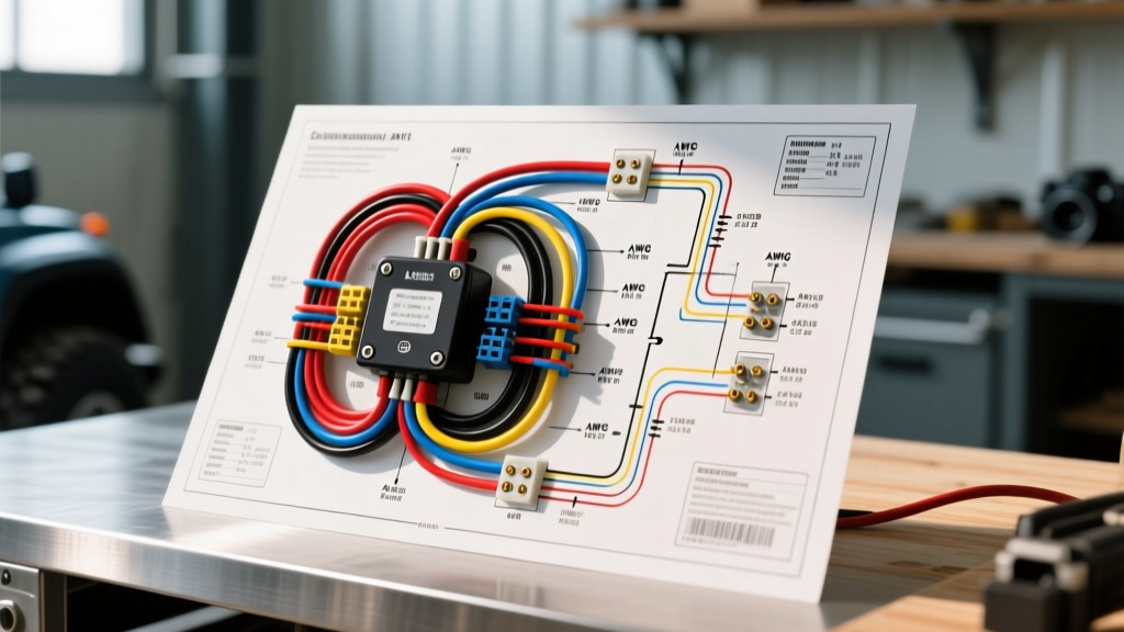
Introduction: Why Integrate a Marine Boat Switch Panel into Automotive Builds?
When constructing custom off-road vehicles, overland expedition trucks, or high-end RVs, standard automotive toggle switches often fail under extreme environmental stress. Dust ingress, high-pressure water washes, and heavy vibration lead to premature contact failure and internal corrosion. This is why professional 12V DC integrators frequently turn to marine-grade hardware. Utilizing a wiring diagram for boat switch panel configurations allows automotive builders to leverage IP68-rated seals, UV-stabilized polycarbonate housings, and heavy-duty silver-cadmium oxide contacts. This complete walkthrough details the exact schematic logic, wire gauge requirements, and relay integration steps needed to adapt a standard Carling Contura V-Series boat switch panel into a high-amperage automotive auxiliary lighting or winch circuit.
Anatomy of the Carling Contura V-Series Switch
The Carling Contura V-Series is the industry standard for marine DC switching. Unlike basic automotive rockers that merely break a single hot wire, these switches feature independent illumination circuits and modular terminal blocks designed for harsh environments. Understanding the terminal pinout is critical before referencing any wiring diagram for boat switch panel setups, as miswiring the illumination pins can short the circuit or burn out the internal LED resistors.
Terminal Pinout Reference Table
| Pin Number | Function | Connection Target | Wire Color (SAE/Marine) |
|---|---|---|---|
| 3 | +12V Input (Source) | Fused Power Distribution Bus | Red (12 AWG) |
| 2 | +12V Output (Load) | Relay Pin 86 (Coil Input) | Blue (16 AWG) |
| 1 | Illumination Ground | Common Ground Busbar | Black (16 AWG) |
| 7 | Second LED Input (Dual) | Dash Light Dimmer Circuit | White (16 AWG) |
Complete Wiring Diagram Walkthrough: 55W LED Light Bar Integration
To demonstrate the practical application of this wiring diagram for boat switch panel architectures, we will route a 55W LED light bar (drawing approximately 4.5 Amps at 14.2V) through a standard ISO Mini Relay (Bosch 5-Pin style). While a 55W light could technically be driven directly through the switch's 20A rating, utilizing a relay ensures the switch only handles the low-current coil trigger. This preserves the switch's internal contacts, minimizes voltage drop across the dashboard, and prevents the heavy-gauge load wires from heating up behind the dash panel.
Step 1: Power Distribution and Circuit Protection
Begin at the vehicle’s auxiliary fuse block or a dedicated marine busbar (such as a Blue Sea Systems ST-Blade). Run a primary 10 AWG red wire from the battery’s positive terminal to a 40A ANL fuse, then to the main busbar. From the busbar, run a 12 AWG red wire to Pin 3 on the boat switch panel. According to SAE J1128 standards for low-tension primary cable, a 12 AWG wire is rated for up to 20A in engine bay environments, providing a massive safety margin for the switch's illumination and trigger circuit.
Step 2: Relay Coil Trigger and Load Routing
Connect a 16 AWG blue wire from Pin 2 (the switched output) of the boat switch panel to Pin 86 on the 5-pin ISO relay. Pin 85 on the relay must be grounded directly to the vehicle chassis using a 16 AWG black wire and a star washer to ensure bare metal contact, stripping away any paint or powder coating. For the high-current load side, run an 8 AWG red wire from the battery (protected by an inline 15A ATO fuse) to Relay Pin 30. Connect Relay Pin 87 to the positive terminal of the LED light bar using 8 AWG wire. Pin 87a (normally closed) remains unused and should be capped with a weather-sealed dummy plug to prevent moisture intrusion into the relay socket.
Step 3: Switch Panel Illumination and Grounding
The internal LEDs of a boat switch panel require a dedicated ground path. Run a 16 AWG black wire from Pin 1 to your central ground busbar. Do not daisy-chain grounds behind the dashboard, as this creates ground loops and causes LED flickering when other high-draw accessories (like a winch or air compressor) engage. If your panel features dual-color LEDs (e.g., Pin 7 for the upper lens), you can wire Pin 7 to the vehicle’s OEM headlight dimmer circuit, allowing the switch panel to dim automatically when the parking lights are activated.
Wire Gauge and Circuit Protection Specifications
Proper wire sizing is non-negotiable in 12V DC systems. Voltage drop over long cable runs (common in extended wheelbase trucks and RVs) can cause relays to chatter or lights to underperform. The following specification chart aligns with ABYC (American Boat & Yacht Council) E-11 standards for marine DC wiring, which are universally adopted in high-end automotive custom builds due to their strict safety margins and derating requirements for bundled wires.
| Circuit Type | Max Amperage | Recommended AWG (Up to 10ft) | Recommended AWG (10-15ft) | Fuse Size |
|---|---|---|---|---|
| Switch Trigger (Pin 2) | 5A | 16 AWG | 14 AWG | 5A ATO |
| Switch Power (Pin 3) | 15A | 12 AWG | 10 AWG | 15A ATO |
| Relay Load (Pin 30-87) | 20A | 10 AWG | 8 AWG | 20A ATO |
| Heavy Load (Winch) | 120A | 2/0 AWG | 2/0 AWG | 150A ANL |
Advanced Troubleshooting: Real-World Failure Modes
Even with a flawless wiring diagram for boat switch panel layouts, environmental and installation variables can introduce faults. Here is how to diagnose the most common issues encountered in the field by off-road and marine technicians.
Symptom: Relay Chatter or Rapid Clicking
Cause: Severe voltage drop between the switch panel and the relay coil (Pin 86), resulting in less than 10.5V reaching the coil. The relay fails to fully pull in the armature, causing it to bounce.
Fix: Upgrade the trigger wire from 16 AWG to 14 AWG. Check for corrosion at the fuse block spade terminals. Use a digital multimeter to measure voltage at Pin 86 while the switch is depressed; it should read within 0.2V of the battery's resting voltage.
Symptom: Switch LED Backfeed (Glows Dimly When Off)
Cause: Inductive kickback or capacitive coupling in long wire runs, or a shared ground path with a high-current device causing a reverse voltage spike that bleeds through the LED resistor network.
Fix: Install a 1N4001 flyback diode across the relay coil (Pin 85 and 86), with the diode stripe facing Pin 86. This absorbs the inductive spike when the switch is opened. Ensure Pin 1 (Ground) has a dedicated, clean chassis ground point torqued to 120 in-lbs.
Symptom: Melted Switch Housing or Discolored Terminals
Cause: Bypassing the relay and routing the full load (e.g., 15A for a large light bar) directly through the switch contacts, combined with a poor crimp on Pin 2 causing localized resistance and heat.
Fix: Never exceed 80% of the switch's continuous rating (16A on a 20A switch). Always use a relay for loads exceeding 10A. Replace the damaged switch and use a ratcheting crimp tool for all non-insulated terminal connections, followed by adhesive-lined marine heat shrink to seal the connection.
Authoritative References and Standards
For further engineering data on 12V DC integration and marine-grade components, consult the following industry standards and manufacturer resources:
- SAE International: SAE J1128 - Low Tension Primary Cable (Defines insulation thickness, thermal ratings, and voltage drop parameters for automotive wire).
- American Boat & Yacht Council: ABYC E-11 AC & DC Electrical Systems (The gold standard for overcurrent protection, wire ampacity derating, and IP68 requirements in harsh environments).
- Carling Technologies: Contura V-Series Actuator Specifications (Official terminal mapping, IP68 ingress protection testing data, and mechanical lifecycle ratings).