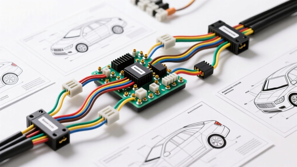
The Shift to Microcontroller-Driven Vehicle Harnesses
Custom automotive electrical systems are rapidly evolving beyond simple relay logic and toggle switches. Whether you are building a restomod with a custom digital dash, integrating a standalone CAN bus gauge cluster, or designing an auxiliary relay box for off-road lighting, microcontrollers are now standard in high-end builds. However, mapping the logical I/O pins of a microcontroller to the physical, harsh environment of a vehicle chassis requires precise planning. This is where specialized Arduino wiring diagram software becomes critical.
Unlike standard residential wiring, automotive harnesses must withstand extreme temperature fluctuations, high-frequency EMI (Electromagnetic Interference), and severe vibration. Translating a digital schematic into a physical harness requires a deep understanding of SAE wire standards, specific crimping tooling, and connector pinouts. In this cost and tool requirements analysis, we evaluate the best software platforms for designing Arduino-based automotive circuits and outline the exact physical tooling required to execute the build.
Arduino Wiring Diagram Software: Cost & Feature Matrix
Choosing the right software dictates not only your upfront licensing costs but also the time required to generate accurate wiring schematics, PCB footprints, and harness routing diagrams. Below is an analysis of the top platforms used by automotive electrical engineers and hobbyists.
| Software Platform | Cost Structure | Automotive Harness Suitability | Best Use Case |
|---|---|---|---|
| Fritzing | $8.00 (One-time) | Low. Lacks advanced harness routing and multi-core cable definitions. | Quick breadboard prototyping of sensor logic before committing to soldered harnesses. |
| KiCad | Free (Open Source) | High. Excellent for designing custom PCB shields that mate directly with Deutsch/Molex connectors. | Designing custom CAN bus nodes and ECU breakout boards with precise footprint mapping. |
| EasyEDA | Free / $10/mo (Pro) | Medium-High. Cloud-based with direct LCSC integration for sourcing automotive-grade relays and MOSFETs. | Collaborative team builds and rapid sourcing of logic-level components for relay drivers. |
| AutoCAD Electrical | ~$285/mo | Very High. Industry standard for full vehicle harness routing, BOM generation, and nailboard diagrams. | Professional shops building complete, chassis-wide wire harnesses from scratch. |
For most enthusiast and semi-professional automotive builders, KiCad offers the highest return on investment. While the learning curve is steep, its ability to generate accurate 3D models of custom PCBs allows you to verify physical clearance against firewall bulkheads and sheet metal before manufacturing. Fritzing, despite its popularity in general maker spaces, falls short in automotive applications because it does not natively support the generation of complex wire harness nailboards or multi-pin connector mapping required for TE Superseal or Deutsch DT series connectors.
Physical Tool Requirements: Translating Code to Copper
Software only provides the logical map. Executing an Arduino-based automotive harness requires specialized physical tooling. Standard hardware store crimpers and PVC wire will fail under hood due to heat degradation and vibration-induced fretting corrosion. According to the SAE J1128 standard, automotive wire must utilize cross-linked polyethylene (TXL or GXL) insulation to withstand under-hood temperatures up to 125°C.
Essential Crimping and Stripping Tooling
- Wire Strippers: Titanium automatic wire strippers (e.g., Capri Tools 20010) calibrated for 22 to 10 AWG TXL wire. TXL insulation is thinner and harder than standard PVC, requiring precise blade depth to avoid nicking the copper strands.
- Deutsch DT Crimpers: A dedicated ratcheting crimper (like the YDT-2 or equivalent IWISS tool) is mandatory for Deutsch solid barrel contacts. A poor crimp on a firewall bulkhead connector will lead to high resistance and voltage drop, causing Arduino brownouts when the starter motor engages.
- TE Superseal 1.5 Crimpers: Required if your Arduino enclosure interfaces directly with OEM-style ECU connectors. These require a specific die to crimp both the wire barrel and the insulation support barrel simultaneously.
- Heat Shrink: Dual-wall, adhesive-lined heat shrink (e.g., 3M FP-301). The inner meltable adhesive seals the wire entry point against moisture ingress, which is critical for undercarriage or engine bay CAN bus nodes.
CAN Bus Integration: Pinouts and Twisted Pair Specs
A common automotive Arduino project is building a custom CAN bus sniffer or digital dash using an MCP2515 CAN controller module. The physical wiring of this module must adhere to ISO 11898-2 high-speed CAN standards to prevent signal reflection and data corruption.
| MCP2515 Pin | Arduino Uno/Nano Pin | Wire Spec & Color Code | Function / Notes |
|---|---|---|---|
| VCC | 5V | 22 AWG TXL (Red) | Logic power. Must be filtered with a 100nF ceramic capacitor to ground to suppress alternator whine. |
| GND | GND | 22 AWG TXL (Black) | Chassis or dedicated ECU ground plane. |
| CS | D10 | 22 AWG TXL (Blue) | SPI Chip Select. Keep trace/wire length under 3 inches to prevent SPI clock skew. |
| SO (MISO) | D12 | 22 AWG TXL (Green) | SPI Master In Slave Out. |
| SI (MOSI) | D11 | 22 AWG TXL (Yellow) | SPI Master Out Slave In. |
| SCK | D13 | 22 AWG TXL (Orange) | SPI Clock. |
| INT | D2 | 22 AWG TXL (Purple) | Interrupt pin. Critical for real-time CAN message parsing without polling delays. |
| CAN H | OBD2 Pin 6 | 22 AWG Twisted Pair (White) | Must be twisted with CAN L at 1 twist per inch. Requires 120-ohm termination resistor at each end of the bus. |
| CAN L | OBD2 Pin 14 | 22 AWG Twisted Pair (Brown) | Differential signaling pair. Never route parallel to high-current ignition wires to avoid EMI. |
High-Current Relay Control: Flyback Diodes and AWG Sizing
Microcontrollers cannot directly drive automotive loads like fuel pumps, cooling fans, or off-road light bars. An Arduino I/O pin can safely source only 20mA to 40mA. To control a standard 30A Bosch-style automotive relay, you must use a logic-level N-channel MOSFET (such as the IRLZ44N) as a low-side switch.
When designing this circuit in your Arduino wiring diagram software, you must include a flyback diode (e.g., 1N4001) wired in reverse bias across the relay coil (Pins 85 and 86). When the MOSFET switches off, the collapsing magnetic field in the relay coil generates a high-voltage reverse spike. Without the diode, this spike will instantly destroy the Arduino's output pin or the MOSFET junction.
Wire Sizing for Relay Circuits:
- Pin 86 (Relay Coil 12V+): 18 AWG TXL, fused at 5A.
- Pin 85 (Relay Coil GND via MOSFET): 18 AWG TXL. The MOSFET drain connects here; the source connects to a clean chassis ground.
- Pin 30 (Relay Load Input): 12 AWG or 10 AWG TXL (depending on load, e.g., 10 AWG for a 40A cooling fan), fused appropriately at the battery.
- Pin 87 (Relay Load Output): 12 AWG or 10 AWG TXL, routed directly to the accessory.
Hidden Costs: Prototyping vs. Production Harness Tooling
When budgeting an Arduino-based automotive project, builders often account for the microcontroller and software but overlook the hidden costs of harness fabrication tooling and automotive-grade connectors. A genuine TE Connectivity Deutsch DT 4-pin connector kit (housing, wedgelock, and solid contacts) costs roughly $4.50 to $6.00 per mating pair. A complete engine management breakout harness utilizing 60 pins can easily exceed $150 in connector costs alone.
Furthermore, professional harness builders use 'nailboards'—physical wooden boards with nails driven in to represent wire routing paths, allowing the builder to wrap, loom, and tape the harness before installing it in the vehicle. While your Arduino wiring diagram software provides the digital schematic, you must factor in the cost of physical loom materials: split braided nylon sleeving, Tesa 51036 PET cloth tape (the OEM standard for engine bay harnesses, as it resists abrasion and heat far better than vinyl electrical tape), and cable ties.
Conclusion
Selecting the right Arduino wiring diagram software is only the first step in building a reliable automotive electrical system. While platforms like KiCad and EasyEDA provide robust, low-cost environments for mapping SPI, CAN, and logic-level circuits, the true cost and success of the project lie in the physical execution. By investing in SAE J1128-compliant TXL wire, ratcheting crimp tools for Deutsch and Superseal connectors, and adhering to strict EMI and flyback protection protocols, you ensure that your custom microcontroller harness will survive the brutal realities of the automotive environment.