Introduction to Kawasaki UTV Electrical Diagnostics
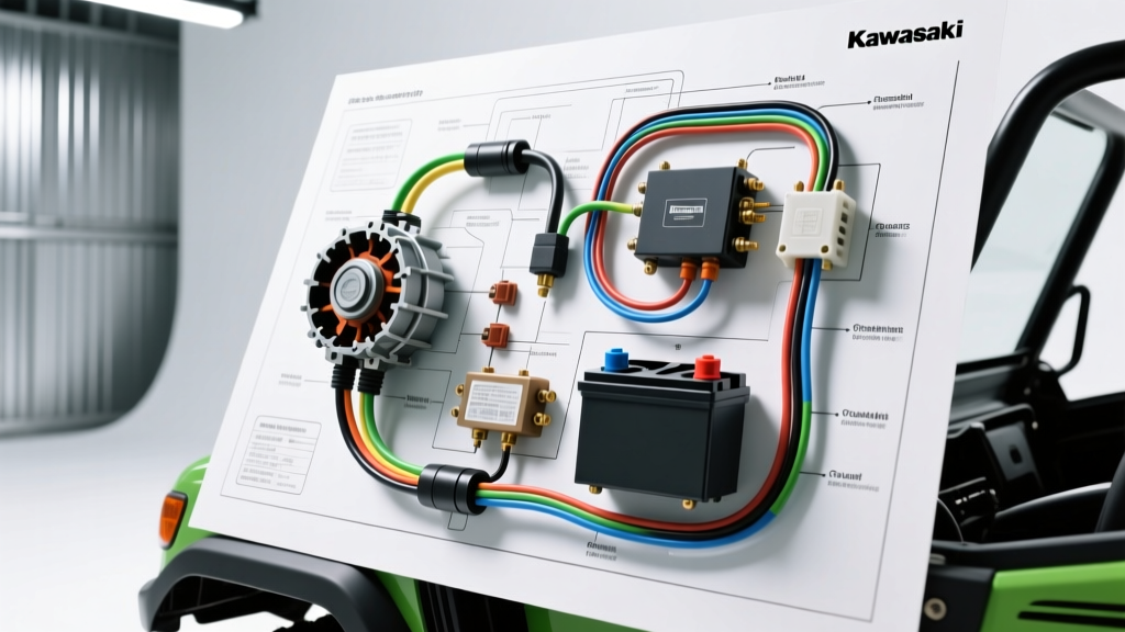
When off-road enthusiasts and fleet mechanics begin their diagnostic journey by searching for a kawasaki wiring diagram free of charge, they are often met with blurry, incomplete forum screenshots that omit critical pinout data and wire gauge specifications. Whether you are maintaining a Kawasaki Mule 4010, a Mule Pro-FXT, or a Teryx KRX, the fundamental architecture of the Kawasaki charging system remains remarkably consistent. It relies on a permanent magnet alternator (stator), a regulator/rectifier (R/R) unit, and a heavy-duty main relay circuit.
This step-by-step troubleshooting flow is designed to bypass the guesswork. By following this structured diagnostic matrix, you can accurately isolate stator failures, rectify voltage drops, and identify parasitic draws using a standard digital multimeter (DMM) and the core circuit logic found in OEM Kawasaki schematics.
Phase 1: Battery Baseline and Main Ground Verification
Before dissecting the stator or R/R, you must establish a known-good baseline. Kawasaki UTVs are notorious for developing hidden corrosion at the main chassis ground, leading to erratic ECU behavior and undercharging.
Step 1.1: Resting and Cranking Voltage
Set your DMM to DC Volts. Measure across the battery terminals. A healthy AGM or Lead-Acid battery must read between 12.6V and 12.8V at rest. If the voltage drops below 10.5V during cranking, the battery has a collapsed cell or the starter motor is drawing excessive amperage (often due to a failing Bendix or starter clutch binding).
Step 1.2: Main Ground Torque and Continuity
Locate the main negative battery cable. In most Mule models, this is a 10 AWG Black wire terminating at the engine block or lower frame rail. Clean the terminal with a wire brush to bare metal. Re-torque the ground bolt to 10 Nm (88 in-lbs). Perform a voltage drop test across the ground circuit with the engine running; a reading above 0.1V indicates high resistance requiring immediate harness repair.
Phase 2: Stator AC Output and Isolation Testing
The stator is the heart of the Kawasaki charging system. It generates raw 3-phase AC voltage, which is then converted to DC. The stator output wires are universally Yellow across almost all Kawasaki motorcycle and UTV platforms.
Step 2.1: 3-Phase AC Voltage Test
Locate the stator output connector, typically a 3-pin Sumitomo HM 090 series sealed waterproof connector situated near the left-side engine cover. Disconnect the harness. Start the engine and set your DMM to AC Volts. Measure the voltage across the three phases:
- Pin 1 to Pin 2 (Yellow to Yellow)
- Pin 2 to Pin 3 (Yellow to Yellow)
- Pin 1 to Pin 3 (Yellow to Yellow)
At idle (approx. 1,200 RPM), you should see 20V to 30V AC. At 3,000 RPM, the output should climb steadily to 50V to 70V AC. If one phase reads significantly lower than the others, the stator has an internal winding short and must be replaced.
Step 2.2: Stator Resistance and Ground Fault Check
With the engine off, switch the DMM to Ohms (Ω). Measure the resistance between the three Yellow stator pins. According to RM Stator technical guidelines, a healthy Kawasaki Mule stator should read between 0.1 Ω and 1.0 Ω. Next, switch the DMM to continuity mode. Place one probe on a Yellow wire and the other on the engine block. The meter must read 'OL' (Open Loop). Any continuity to ground indicates the stator epoxy has cracked, allowing copper windings to short against the stator core, which will instantly destroy a new regulator/rectifier if not addressed.
Phase 3: Regulator/Rectifier (R/R) Verification
Kawasaki UTVs utilize either a traditional Shunt-style R/R or a newer MOSFET design. Shunt regulators dissipate excess stator energy as heat, making them highly prone to thermal failure in slow-moving, low-airflow UTV environments like the Mule.
Step 3.1: DC Output and Ripple Test
Reconnect the stator and R/R harnesses. Start the engine and measure DC voltage at the battery. It should read 14.2V to 14.8V at 2,500 RPM. If the voltage exceeds 15.0V, the R/R has failed open, risking severe damage to the ECU and LED lighting. Switch your DMM to AC Volts and measure the battery again. If you read more than 0.5V AC (ripple voltage), the rectifier diodes inside the R/R are leaking AC current into the DC system.
Step 3.2: The MOSFET Upgrade Path
If your free Kawasaki wiring diagram shows a 4-pin or 5-pin shunt regulator, consider upgrading to a MOSFET unit (such as the RM30300H). MOSFET regulators do not short the stator windings to ground to regulate voltage; they simply stop drawing power, keeping the stator running cooler and extending its lifespan. The wiring adaptation requires splicing the OEM Red (Battery +) and Black (Ground) wires using 12 AWG marine-grade heat shrink butt connectors, ensuring the main charge wire can handle the 30A+ continuous load.
Kawasaki Mule Charging Circuit Reference Matrix
| Circuit Function | OEM Wire Color | AWG Size | Connector Type | Diagnostic Target |
|---|---|---|---|---|
| Stator Phase 1, 2, 3 | Yellow (x3) | 14 AWG | Sumitomo 3-Pin Sealed | AC Voltage & Winding Resistance |
| Main Battery Feed (R/R) | Red / Red-White | 10 AWG | Ring Terminal / 4-Pin | DC Charging Voltage (14.2V-14.8V) |
| Main Chassis Ground | Black / Black-Yellow | 10 AWG | Ring Terminal (M8) | Voltage Drop (<0.1V) |
| Ignition Switched 12V | White / Brown | 16 AWG | Standard 064 Series | R/R Activation / ECU Wake |
Phase 4: Parasitic Draw and Accessory Troubleshooting
If your Mule battery is dead after sitting for 48 hours, you have a parasitic draw. Modern Kawasaki UTVs feature digital dash displays, GPS modules, and EPS (Electric Power Steering) controllers that can fail to enter sleep mode.
Step 4.1: Inline Amperage Testing
Turn the ignition off and remove the key. Disconnect the negative battery terminal. Set your DMM to the 10A DC setting. Place the red probe on the disconnected negative cable and the black probe on the negative battery post. Wait 60 seconds for the ECU and EPS modules to power down. A normal parasitic draw should be under 5 milliamps (0.005A). If the draw is higher, begin pulling fuses one by one from the main fuse block near the battery while watching the DMM. When the amperage drops to zero, the circuit on the removed fuse contains the fault.
Step 4.2: EPS and Winch Relay Isolation
The two most common culprits for Kawasaki UTV parasitic draws are aftermarket winch solenoids and failing EPS relays. Winch contactors often develop internal carbon tracking, allowing micro-currents to bleed to ground. Always wire aftermarket winches through a heavy-duty mechanical cutoff switch or an isolated marine relay to prevent phantom battery drain.
Symptom-Cause-Fix Decision Tree
- Symptom: Battery reads 12.6V at rest, drops to 11.5V at 3000 RPM.
Cause: Stator open circuit or Shunt R/R thermal failure.
Fix: Test Stator AC output. If AC is good, replace R/R with a MOSFET upgrade kit. - Symptom: Battery reads 15.5V+ at high RPM, headlights blow out.
Cause: R/R ground wire severed or corroded; regulator cannot dump excess voltage.
Fix: Repair 10 AWG Black ground wire to chassis; verify SAE J1128 compliance for replacement wire. - Symptom: Engine stalls when cooling fan engages.
Cause: Voltage drop across main harness due to undersized accessory wiring.
Fix: Install a dedicated 30A relay for the cooling fan, triggering it off a switched 16 AWG signal wire but pulling main current directly from the battery via 12 AWG wire.
Conclusion and Schematic Best Practices
Relying on a generic kawasaki wiring diagram free from an unverified source can lead to misdiagnosed components and expensive parts-swapping. By understanding the raw physics of the 3-phase stator, the thermal limitations of shunt regulators, and the strict torque and grounding requirements of the Kawasaki chassis, you can diagnose electrical faults with dealer-level precision. Always use dielectric grease on all Sumitomo connectors post-repair, and refer to the official Kawasaki Owner's Manual portal for model-specific fuse block layouts and torque specifications.