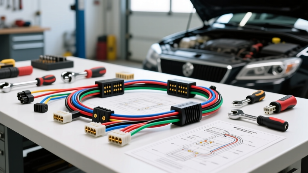
The Hidden Dangers of Unverified Free Car Electrical Wiring Diagrams
Every DIY mechanic and seasoned technician has searched for free car electrical wiring diagrams to save time and money. While factory service manuals (FSM) and OEM scan tool subscriptions cost hundreds of dollars annually, free resources found on forums, third-party databases, and image-hosting sites can seem like a goldmine. However, relying on unverified schematics introduces severe risks to both the vehicle's electronic architecture and the technician's personal safety. Modern vehicles utilize complex multiplexed networks, high-voltage hybrid systems, and sensitive supplemental restraint systems (SRS) that demand absolute precision.
The primary danger of using generic or outdated free car electrical wiring diagrams is the omission of mid-year production splits. For example, a 2018 Ford F-150 might feature entirely different Body Control Module (BCM) pinouts depending on whether it was built in early 2018 or late 2018, driven by supply chain shifts in Delphi Packard connector cavities. If you use a generic diagram that does not account for your specific VIN build date, you risk back-probing the wrong cavity, potentially sending 12V reference voltage directly into a 5V logic circuit, instantly frying the PCM.
Top 5 Fatal Wiring Mistakes Made from Misread Diagrams
When technicians and DIYers misinterpret free schematics, the resulting errors often cascade through the vehicle's CAN bus network. Below are the most common and destructive mistakes made when working from incomplete diagrams.
1. Ignoring Wire Gauge (AWG) and Amperage Limits
Many free diagrams display wire colors and routing but fail to specify the American Wire Gauge (AWG) or the circuit's maximum amperage draw. Upgrading a component or splicing in an accessory without verifying the SAE J1128 Standard for low-tension primary cable limits will result in melted insulation, voltage drops, or electrical fires.
| AWG Size | Max Amps (SAE J1128) | Typical Automotive Application |
|---|---|---|
| 18 AWG | 6A | Sensor signals, CAN bus, module wake-up lines |
| 16 AWG | 10A | Interior lighting, low-draw solenoids, infotainment |
| 14 AWG | 15A | Fuel pumps, power windows, HVAC blower relays |
| 12 AWG | 20A | Heated seats, high-draw lighting, ABS valving |
| 10 AWG | 30A | ECU main power feeds, high-amperage accessory circuits |
2. Splicing into High-Speed CAN Bus Networks
Free car electrical wiring diagrams often show the OBD2 Data Link Connector (DLC) pins 6 (CAN-High) and 14 (CAN-Low) as standard wires. According to the SAE J1962 DLC Standard, these are high-speed multiplexed network lines operating at 500 kbps. Splicing into these twisted-pair wires using standard crimp butt-connectors introduces parasitic capacitance and alters the characteristic 120-ohm impedance. This immediately throws U0001 (High Speed CAN Communication Bus) codes and can knock the transmission control module (TCM) offline. Always use dedicated CAN bus breakout adapters or solder-seal splices if network access is absolutely mandatory.
3. Bypassing Ground Splice Packs
General Motors vehicles frequently utilize ground splice packs (e.g., SP205 or SP305) to tie multiple module grounds together before routing them to a single chassis ground point like G101. Free diagrams often simplify this, showing individual wires going straight to ground. If a technician cuts the harness to repair a single frayed ground wire and bypasses the splice pack, they inadvertently isolate the other modules sharing that pack, causing cascading communication failures and phantom sensor codes.
4. Confusing Relay Coil vs. Switch Terminals
ISO standard mini-relays feature pins 85 and 86 for the low-amperage control coil, and pins 30 and 87 for the high-amperage switch side. Misreading a poorly scanned free diagram can lead to wiring a high-draw load (like a 40A radiator fan) through the BCM's low-side driver coil circuit. This will instantly overload the BCM's internal transistor, requiring a complete module replacement and programming session.
5. Misinterpreting OEM Wire Color Nomenclature
Wire color codes vary drastically between manufacturers, and free diagrams rarely include a legend. For instance, a Black wire with an Orange tracer is denoted as BK/OG in Ford manuals, BLK/ORG in GM manuals, and B/O in Toyota manuals. Assuming a universal standard leads to tracing the wrong circuit, especially in dense harnesses where multiple wires share similar base colors.
Essential Safety Protocols Before Cutting or Splicing
Electrical safety goes far beyond avoiding short circuits. Modern vehicles are equipped with explosive pyrotechnic devices and high-voltage architecture that demand strict adherence to safety protocols.
SRS and Airbag Module Wait Times
Any wire tracing near yellow connectors involves the Supplemental Restraint System (SRS). The NHTSA Airbag Safety Guidelines and OEM service manuals mandate that simply disconnecting the 12V battery is not enough. The SRS Sensing and Diagnostic Module (SDM) contains a backup capacitor designed to deploy airbags even if the main battery is destroyed in a crash. You must disconnect the negative battery terminal and wait a minimum of 15 minutes (up to 30 minutes on late-model EVs and PHEVs) for the capacitor to drain before back-probing or cutting any yellow harnesses.
Voltage Drop Testing Over Continuity Testing
A common mistake when using free diagrams to diagnose a ground fault is relying on a multimeter's continuity beep. A single strand of 18 AWG copper wire will show continuity and beep, but it cannot carry the 15A required by a fuel pump relay. Instead, perform a dynamic voltage drop test. With the circuit loaded and active, measure the voltage between the component's ground terminal and the negative battery post. A reading above 0.1V indicates excessive resistance, corrosion, or a failing splice pack that a simple continuity test would miss.
How to Validate Your Diagram Against the Physical Harness
Never trust a free car electrical wiring diagram blindly. Always validate the schematic against the physical vehicle using the following expert techniques:
- Connector Cavity Counting: OEM diagrams use a specific numbering system for connector cavities (e.g., Pin 1 is often top-left, but some Molex MX150 connectors number sequentially in a spiral). Use a dental pick and a magnifying glass to verify the cavity number molded into the plastic connector housing before inserting a T-pin.
- Breakout Boxes: When diagnosing PCM or TCM faults, use a harness breakout box. This allows you to measure pin voltages and resistances without piercing the wire insulation, which can introduce moisture and cause future green-crust corrosion.
- Verify Fuse Amperage: If the free diagram indicates a 20A fuse, but the physical fuse block contains a 30A fuse, stop immediately. A previous owner or technician may have upsized the fuse to mask a dead short, meaning the wire gauge is no longer protected against thermal runaway.
By treating free car electrical wiring diagrams as preliminary references rather than absolute truth, and by rigorously applying SAE standards and OEM safety protocols, you can diagnose complex electrical faults without risking module destruction or personal injury.