The Upgrade Context: Adding Auxiliary Lighting to Off-Road Vehicles
Upgrading a Jeep Wrangler, Ford F-150, or Toyota Tacoma with auxiliary lighting is one of the most popular modification projects for off-road enthusiasts. Whether you are mounting three 4-inch LED pod lights on a roof rack, installing a trio of rock lights on the chassis, or wiring three ditch lights to your A-pillars, managing the electrical load is critical. Searching for a reliable wiring diagram for 3 lights one switch setup often leads to oversimplified sketches that ignore voltage drop, modern CAN-bus systems, and proper waterproofing. In this comprehensive guide, we will detail the exact methodology to wire three auxiliary lights to a single cabin switch using a heavy-duty automotive relay harness, ensuring your modification is safe, reliable, and trail-ready.
Why Factory Switches and Direct Wiring Fail
A common mistake in DIY auxiliary lighting projects is attempting to run the full amperage of three LED lights directly through a dashboard toggle switch. Most standard automotive toggle switches are rated for a maximum of 10 to 15 amps. While modern LED pods are highly efficient, a trio of high-output 40W LED pods will draw roughly 10 amps combined (assuming a 12V system). Pushing a switch to its absolute maximum rating generates excessive heat at the terminal contacts, leading to voltage drop, melted plastic housings, and eventual switch failure.
Furthermore, running 12-gauge wire from the engine bay, through the firewall, into the cabin, and back out to the lights introduces unnecessary resistance and creates multiple points of failure. The correct approach utilizes a wiring diagram for 3 lights one switch that incorporates a standard Bosch-style SPST (Single Pole, Single Throw) 4-pin or 5-pin automotive relay. This isolates the high-current load to the engine bay while the cabin switch only handles the low-current trigger signal.
Bill of Materials and AWG Wire Sizing Chart
Before cutting into your vehicle's harness, you must select the correct wire gauge. According to SAE J1128 standards for low-tension primary cables, wire gauge must be selected based on the total amperage and the total length of the wire run to mitigate voltage drop. For off-road applications, we strongly recommend using GXL or TXL cross-linked polyethylene (XLPE) insulated wire rather than standard PVC, as it withstands engine bay temperatures up to 150°C.
| Circuit Segment | Recommended AWG | Max Ampacity | Connector Type | Insulation / Protection |
|---|---|---|---|---|
| Battery to Relay (Pin 30) | 10 AWG GXL | 30A | Ring Terminal (8mm) | Split Loom & ATC Fuse |
| Relay to Lights (Pin 87) | 12 AWG GXL | 20A | Deutsch DT 2-Pin | Adhesive Heat Shrink |
| Switch Trigger (Pin 86) | 16 AWG or 18 AWG | 5A | Metri-Pack 280 | Firewall Grommet Seal |
| Ground Circuits (Pin 85 & Lights) | 12 AWG GXL | 20A | Ring Terminal (6mm) | Star Washer & Bare Metal |
Step-by-Step Wiring Diagram for 3 Lights One Switch
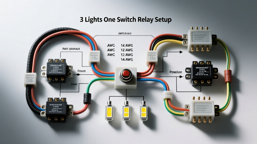
The core of this modification relies on a standard 4-pin automotive relay. The relay acts as a remote-controlled heavy-duty switch. Below is the precise pinout and routing strategy for your harness.
Step 1: The High-Current Power Circuit
Begin at the vehicle's battery positive terminal. Crimp a 10 AWG ring terminal to a length of red 10 AWG wire. Crucial: Within 8 inches of the battery terminal, install an inline ATC fuse holder equipped with a 15-amp blade fuse. This protects the entire circuit in the event of a short to ground. Route this wire to Pin 30 (the common power input) on your relay. Pin 30 will now have constant 12V+ battery power.
Next, connect a length of 12 AWG red wire to Pin 87 (the normally open output). This wire will carry the switched 12V+ power out to your three auxiliary lights.
Step 2: The Control Circuit (Switch to Relay)
Pin 86 is the relay coil positive trigger. Run a 16 AWG wire from Pin 86 through the vehicle's firewall using an existing rubber grommet. Pierce the rubber with a small pick, feed the wire through, and seal the hole with automotive silicone to prevent water and carbon monoxide ingress. Inside the cabin, connect this wire to the output terminal of your dashboard toggle switch. The input terminal of the switch should be wired to an ignition-switched 12V+ source (such as the rear accessory power outlet or a fuse tap on an ignition-controlled circuit). This ensures your lights cannot be left on accidentally, draining the battery.
Step 3: Grounding the System
Pin 85 is the relay coil ground. Connect a 12 AWG black wire from Pin 85 to a clean, unpainted chassis ground in the engine bay. Use a star washer to bite through the clear coat or powder coating, ensuring a solid electrical connection to bare metal. Similarly, all three auxiliary lights must have their ground wires terminated to the chassis using the same bare-metal star washer technique. Never rely on self-tapping screws into painted sheet metal for grounds; the resistance will cause severe voltage drop and flickering.
Parallel Splitting Techniques: Wiring the 3 Lights
When executing a wiring diagram for 3 lights one switch, the most common point of failure is the splice where the single 12 AWG wire from Pin 87 splits into three separate wires for the lights. Do not use twist-on wire nuts or electrical tape, as vibration and moisture will destroy these connections off-road.
You have two professional options for splitting the load:
- Marine Distribution Block: Mount a small 4-post marine-grade distribution block (with tin-plated copper busbars) near the lights. Run the 12 AWG feed from Pin 87 into the block, and run three individual 14 AWG or 12 AWG wires from the block to each light. Seal the block with a silicone-filled cover.
- Sealed Heat-Shrink Splices: Use adhesive-lined marine heat shrink butt connectors. Strip the main feed wire, crimp all three light positive wires into a single 12-to-10 AWG step-down butt splice, and apply heat until the adhesive oozes from the ends. This creates a completely waterproof, vibration-proof parallel circuit.
By wiring the three lights in parallel, each light receives the full 12V-14V system voltage. If wired in series, the voltage would be divided by three, resulting in extremely dim lights and uneven current distribution.
Modern Vehicle Challenges: CAN-Bus and PWM Headlight Circuits
If you are performing this upgrade on a modern truck (e.g., 2015+ Ford F-150, 2019+ Ram 1500, or newer GM Silverado), you must be cautious if you intend to use your factory headlight circuit as the trigger for the switch. Modern vehicles use Pulse Width Modulation (PWM) to control headlight voltage, rapidly pulsing the power to dim the lights or save energy. A standard relay coil cannot interpret PWM signals; it will chatter, click rapidly, and eventually burn out the relay coil or the vehicle's Body Control Module (BCM).
If your wiring diagram for 3 lights one switch requires the lights to turn on automatically with the high beams, you must install a PWM filter module or an optical isolation relay between the factory headlight wire and your dashboard switch. Alternatively, bypass the headlight trigger entirely and use a dedicated, standalone toggle switch wired to an ignition-switched fuse tap, which provides a clean, constant 12V+ trigger signal.
Troubleshooting Common Off-Road Light Issues
- Symptom: Lights flicker when the engine is idling but brighten when revving.
Cause & Fix: This indicates a severe voltage drop on the power or ground side. Check the ground connections for paint or rust. Use a multimeter to measure the voltage drop across the ground wire; it should read less than 0.1V under load. - Symptom: The relay clicks, but the lights do not turn on.
Cause & Fix: The control circuit (Pins 85 and 86) is functioning, but the high-current circuit is failing. Check the ATC fuse near the battery. Inspect Pin 30 and Pin 87 terminals on the relay for loose crimps or corrosion. - Symptom: The dashboard switch feels hot to the touch.
Cause & Fix: The switch is wired directly to the lights without a relay, or the relay coil is shorted, pulling high amperage through the switch. Rewire using the relay isolation method detailed above.
Authoritative References and Further Reading
For deeper insights into automotive electrical standards and relay specifications, consult the following industry resources:
- SAE International - J1128 Low Tension Primary Cable Standard: Essential reading for understanding wire insulation types (GXL, TXL, SXL) and temperature ratings in engine bay environments.
- Bosch Mobility Solutions - Automotive Relays: Technical datasheets for standard ISO mini and micro relays, including coil resistance specs and maximum switching capacities.
- Painless Performance Products - Wiring Manuals: Comprehensive guides on firewall routing, crimping techniques, and off-road harness waterproofing methodologies.
By adhering to this wiring diagram for 3 lights one switch methodology, utilizing the correct AWG wire, and respecting modern vehicle electrical architectures, your auxiliary lighting upgrade will provide thousands of miles of reliable, high-output illumination.