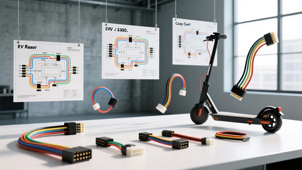
Decoding the Electrical Architecture of Electric Kick Scooters
When servicing, repairing, or upgrading personal electric vehicles (PEVs), obtaining an accurate wiring diagram for a Razor scooter is the critical first step. Unlike complex automotive CAN-bus networks, Razor scooters utilize relatively simple, low-voltage DC pulse-width modulation (PWM) circuits. However, the variations between models—specifically the 24V entry-level platforms and the 36V performance platforms—dictate entirely different component selection strategies. This guide serves as a comprehensive product comparison and selection matrix, helping you choose the correct replacement speed controllers, battery packs, and throttles based on the specific wiring schematics of your scooter.
According to Razor's official support documentation, the core electrical loop consists of the battery pack, main power switch, speed controller, throttle assembly, brake inhibit switch, and the brushed DC motor. Understanding how these components interface is essential for selecting compatible aftermarket upgrades or OEM replacement parts.
Platform Comparison: Selecting the Right Base Model
Before purchasing replacement wiring harnesses or controllers, you must identify your scooter's voltage class and motor wattage. Selecting a 36V controller for a 24V harness will result in immediate overvoltage failure of the throttle's Hall-effect sensor and the brake microswitch. Below is a comparison of the three most common Razor electrical platforms to guide your parts selection.
| Model Platform | Nominal Voltage | Motor Wattage | Primary Wire Gauge | Throttle Type | Best Use Case |
|---|---|---|---|---|---|
| E100 / E200 Series | 24V (2x 12V SLA) | 100W - 125W | 14 AWG | 3-Pin SM Connector | Entry-level OEM replacement, basic SLA battery swaps. |
| E300 / MX350 Series | 36V (3x 12V SLA) | 250W - 300W | 12 AWG | 3-Pin SM Connector | Mid-range upgrades, Li-ion battery conversions. |
| Crazy Cart / MX650 | 36V (3x 12V SLA) | 500W - 650W | 10 AWG | 3-Pin XLR / SM | High-current MOSFET controller upgrades, drift builds. |
24V vs 36V System Selection Guide
24V Systems (E100, E200, A-Series)
The 24V architecture is the most prevalent in Razor's lineup. The wiring diagram for a Razor scooter in this class typically routes two 12V 7Ah Sealed Lead Acid (SLA) batteries in series. When selecting a replacement speed controller for a 24V system, you must choose a unit rated for at least 15A continuous current. The OEM wiring harness uses 14 AWG wire for the main battery-to-controller loop, which is sufficient for the 100W motor (drawing roughly 8-10A under load). If you are selecting an upgrade battery, a 24V 10Ah LiFePO4 pack can utilize the existing 14 AWG harness without requiring a rewiring of the deck, provided the BMS (Battery Management System) limits continuous discharge to 15A.
36V Systems (E300, MX350, Dirt Quad)
The 36V platforms demand heavier-duty component selection. The wiring diagram for these models incorporates three 12V SLA batteries and a heavier-gauge harness (typically 12 AWG for battery leads, 10 AWG for motor leads). When selecting a 36V controller, ensure it features a dedicated brake-inhibit pin. In 36V systems, the kinetic energy and momentum are significantly higher; relying solely on PWM throttling without a hardware brake cutoff is a safety hazard. Furthermore, if you are upgrading to a 36V 15Ah Lithium-Ion pack, you must select a harness with Anderson Powerpole connectors (rated for 30A+) rather than the OEM ceramic block spade terminals, which are prone to thermal melting at sustained 20A draws.
Speed Controller Pinouts and Connector Selection
The speed controller is the brain of the scooter. When comparing aftermarket controllers (such as those from Electric Scooter Parts), you must match the pinout configuration to your existing throttle and brake switches. Below is the standard pinout matrix used across most Razor 24V and 36V controllers.
| Wire Color | Function | Connector Type | Selection Notes |
|---|---|---|---|
| Red (Thick) | B+ (Battery Positive) | Spade / Ring Terminal | Must match battery positive; fuse inline recommended. |
| Black (Thick) | B- (Battery Negative) | Spade / Ring Terminal | Common ground for motor and logic circuits. |
| Blue | Motor + | Spade Terminal | Connects to positive motor brush. |
| White / Yellow | Motor - | Spade Terminal | Connects to negative motor brush; handles PWM switching. |
| Red (Thin) | Throttle 5V VCC | 3-Pin SM (Male) | Provides logic power to Hall-effect sensor. |
| Black (Thin) | Throttle Ground | 3-Pin SM (Male) | Logic ground; do not confuse with high-current B-. |
| Green / White | Throttle Signal | 3-Pin SM (Male) | Variable voltage (0.8V to 3.6V); select linear Hall throttle. |
| Orange / Gray | Brake Inhibit | 2-Pin SM | Normally Closed (NC) switch; opens circuit to halt PWM. |
Wire Gauge (AWG) and Harness Selection Standards
When fabricating a custom harness or selecting a replacement wiring loom, adherence to proper AWG (American Wire Gauge) standards is non-negotiable to prevent voltage drop and fire hazards. According to SAE J1128 standards for low-tension primary cables, wire selection must account for both continuous amperage and the thermal environment inside the scooter's enclosed deck.
- 10 AWG Wire: Required for 36V systems drawing over 20A continuously (e.g., Crazy Cart, MX650). Ideal for the motor-to-controller loop where PWM switching generates high-frequency heat.
- 12 AWG Wire: The standard for 36V E300 battery packs and main power loops up to 20A.
- 14 AWG Wire: Suitable for 24V E100 systems and 36V charge circuits. Do not use for main motor leads on 250W+ motors.
- 18-22 AWG Wire: Reserved exclusively for low-current logic signals, including the 3-pin throttle harness, brake inhibit switch, and battery indicator LEDs.
When selecting replacement wire, always choose stranded copper with cross-linked polyethylene (XLPE) or PVC insulation rated for at least 105°C, as the ambient temperature inside a steel scooter deck can exceed 50°C during summer operation.
Component Upgrade Selection Matrix
For enthusiasts looking to modify their scooter based on the wiring diagram, component selection must be balanced. Upgrading one part without considering the electrical limits of the others will result in failure.
1. Throttle Selection
Razor scooters use a linear Hall-effect throttle. When selecting a replacement, verify the magnet orientation. Some aftermarket throttles output a reverse voltage curve (3.6V at idle, 0.8V at full throttle). You must select a throttle that matches your controller's logic mapping, or the scooter will accelerate upon being powered on, posing a severe safety risk.
2. Speed Controller (MOSFET) Selection
OEM controllers use basic bipolar junction transistors (BJTs) or low-tier MOSFETs that fail under sustained hill-climbing loads. When selecting an upgrade controller, look for units utilizing IRFB4110 or IRFB3077 MOSFETs. These components handle high current with minimal thermal throttling. Ensure the replacement controller includes a 'soft-start' capacitor circuit to prevent inrush current from tripping the main battery BMS or blowing the inline fuse.
3. Battery Chemistry Selection
Transitioning from SLA to Lithium-Ion (Li-ion) or Lithium Iron Phosphate (LiFePO4) requires careful wiring diagram modifications. SLA batteries can deliver massive, unregulated inrush currents. Li-ion packs rely on a BMS. If you select a 36V Li-ion pack, you must wire a pre-charge resistor (typically 100 ohms, 5W) across the main power switch contacts in the wiring diagram to prevent the controller's input capacitors from drawing a massive spark that trips the BMS into protection mode upon startup.
Troubleshooting Decision Tree
Use this structured diagnostic path when your wiring diagram indicates a break in the circuit, but the physical wires appear intact.
- Symptom: Scooter powers on, lights illuminate, but motor does not engage.
Diagnostic Step: Check the brake inhibit switch. Razor wiring diagrams place this switch in series with the controller's logic ground or signal line. If the NC brake switch is stuck open, the controller assumes the brakes are applied and disables the PWM output. Bypass the 2-pin brake connector to test. - Symptom: Motor stutters or cuts out under load, but runs fine on a stand.
Diagnostic Step: Voltage drop across the main harness. Use a multimeter to measure B+ and B- at the controller terminals while applying load. If voltage drops below 22V (on a 24V system) or 30V (on a 36V system), the battery pack has a weak cell, or the 14 AWG wiring harness has a corroded spade terminal causing high resistance. - Symptom: Throttle feels dead; no voltage on signal wire.
Diagnostic Step: Measure the Red and Black thin wires at the 3-pin SM connector. You must read exactly 4.8V to 5.1V. If you read 0V, the controller's internal 5V voltage regulator has failed, requiring a complete controller replacement.
Final Selection Advice
Whether you are restoring a vintage E100 or building a high-torque E300 drift scooter, the wiring diagram for a Razor scooter is your blueprint for success. Always prioritize connector integrity—crimp and solder all spade terminals, and use heat-shrink tubing to prevent short circuits against the metal deck. By matching your component selections to the specific voltage, amperage, and pinout requirements outlined in this guide, you ensure a reliable, safe, and high-performance electrical system.