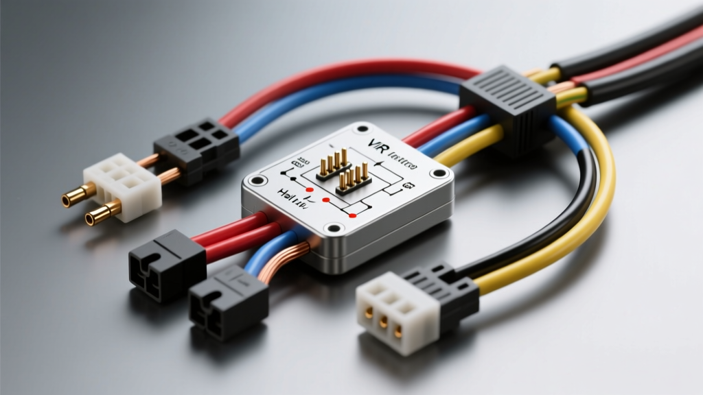
The Critical Role of CKP Integration in Engine Swaps
When executing a complex engine swap—such as dropping a GM LS, Ford Coyote, or Honda K-Series into a custom chassis—the crankshaft position sensor (CKP) is the single most critical input for your standalone ECU. Without a pristine, noise-free crank signal, the ECU cannot calculate engine speed or determine base ignition timing, resulting in a no-start condition or catastrophic misfires. This comprehensive crankshaft sensor wiring diagram and modification guide is engineered for fabricators and tuners building custom harnesses for aftermarket ECUs like Megasquirt, Haltech, or Motec.
Factory wiring harnesses are designed for specific chassis routing and OEM EMI (Electromagnetic Interference) environments. When you relocate an engine, route harnesses near aftermarket headers, or introduce high-output ignition systems, the factory CKP wiring often falls victim to noise. Building a custom, shielded harness from the sensor connector directly to the ECU is the gold standard for swap projects.
Understanding Sensor Topologies: VR vs. Hall Effect
Before cutting and crimping wires, you must identify the topology of your crankshaft sensor. Swapping between engine families often means adapting different sensor types to your chosen standalone ECU.
2-Wire Variable Reluctance (VR) Sensors
Commonly found on GM LS engines (24x and 58x reluctors) and many older distributor-less setups, VR sensors are passive magnetic pickups. They generate an alternating current (AC) sine wave as the reluctor wheel teeth pass the magnetic core. The amplitude (voltage) and frequency of the signal increase proportionally with engine RPM. At cranking speeds, a VR sensor might only output 0.5V to 1.5V AC, but at 7,000 RPM, it can exceed 50V AC. Because they are passive, they require no external power or ground, only a twisted pair of signal wires returning to the ECU's differential VR input circuit.
3-Wire Hall Effect Sensors
Hall effect sensors (common on Ford Coyote, Chrysler HEMI, and Honda K-Series engines) are active solid-state devices. They require a 5V to 12V power supply, a dedicated ground, and output a 0-5V DC square wave. The ECU reads the sharp rising and falling edges of this square wave to determine RPM. Because Hall sensors output a fixed voltage regardless of RPM, they provide excellent cranking signal clarity, but they are highly susceptible to EMI if the power and signal wires are not properly isolated.
Universal Crankshaft Sensor Wiring Diagram & Pinout
The following wiring specification table outlines the blueprint for fabricating a custom harness for a GM LS 58x VR crankshaft sensor, adapting it to a generic standalone ECU differential VR input. This setup is the benchmark for rear-wheel-drive V8 swap projects.
| Sensor Pin | Function | Custom Harness Wire Color | AWG Size | ECU Destination / Notes |
|---|---|---|---|---|
| Pin A | CKP Signal (+) | White (Shielded Pair 1) | 22 AWG | ECU VR+ Input (e.g., Pin 24) |
| Pin B | CKP Signal (-) | White/Black Stripe (Shielded Pair 1) | 22 AWG | ECU VR- Input (e.g., Pin 49) |
| N/A | Shield Drain Wire | Bare Copper / Silver | 24 AWG | ECU Sensor Ground (Pinned at ECU ONLY) |
| N/A | Outer Loom | Nylon Braided Sleeving | N/A | Protects from abrasion and exhaust heat |
Note: If your project utilizes a 3-wire Hall Effect sensor, you must upgrade the power and ground lines to 20 AWG to prevent voltage drop over long custom harness runs, while keeping the signal wire at 22 AWG. Always consult your specific Megasquirt MS3 Wiring Manual or Haltech Wiring Best Practices for exact ECU pin assignments.
Shielding, Twisted Pairs, and the Ground Loop Rule
The most common failure point in custom swap harnesses is EMI interference from the starter motor, alternator, and ignition coils. The CKP signal wire acts as an antenna if not properly shielded. To defeat this, you must use Shielded Twisted Pair (STP) cable, such as Belden 8723 or equivalent automotive-grade Deutsch spec wire.
Why Twisted Pairs?
Twisting the Signal (+) and Signal (-) wires together (aim for 4 to 6 twists per inch) ensures that any external magnetic interference induces an equal and opposite voltage in both wires. The ECU's differential input circuit reads only the difference between the two wires, effectively canceling out the induced noise (Common Mode Rejection).
The Shield Drain Wire Protocol
The metallic foil or braided shield surrounding the twisted pair must be terminated correctly to act as a Faraday cage. Critical Rule: The shield drain wire must be grounded at the ECU end ONLY. If you ground the shield at both the sensor and the ECU, you create a ground loop. Because the engine block and the ECU chassis often sit at slightly different electrical potentials, a ground loop will cause current to flow through the shield, injecting alternator whine and ignition noise directly into your crank signal. Solder the drain wire to the ECU's dedicated analog sensor ground pin, and wrap the sensor end of the drain wire in heat shrink to prevent it from shorting to the engine block.
Cranking Voltage Drop and Starter EMI
During an engine swap, the physical distance between the battery, the starter motor, and the ECU is often extended. When the starter engages, it can draw 200+ amps, causing a massive voltage drop in the chassis ground and generating severe broadband EMI. If your custom harness is routed near the starter solenoid, the VR sensor's low-amplitude cranking signal (often less than 1V AC) will be completely drowned out by the starter's electromagnetic field.
Modification Best Practice: Route the CKP shielded harness on the opposite side of the engine block from the starter motor. If you must cross paths with high-current starter cables, do so at a strict 90-degree angle to minimize inductive coupling. Furthermore, ensure your engine block ground strap is upgraded to a minimum of 2/0 AWG flexible copper braid to stabilize the electrical potential between the block and the chassis.
Signal Conditioning: Adapting Mismatched Sensors
A frequent hurdle in modification projects is mismatching a sensor to an ECU input. For example, adapting a Ford Coyote 3-wire Hall effect sensor to an older ECU that only accepts 2-wire VR inputs.
- Hall to VR Conversion: You cannot simply wire a Hall sensor to a VR input. You must use a signal conditioner module (such as the JBPerformance VR converter or MSD 8615). These modules power the Hall sensor and translate the 0-5V square wave into a simulated AC sine wave that the ECU's VR conditioning circuit can read.
- VR to Hall Conversion: If your ECU requires a 5V square wave but you are using an LS VR sensor, the ECU's internal VR conditioner will handle the zero-crossing detection. However, you must ensure the ECU's VR bias resistors are enabled in the software to pull the signal up, allowing the ECU to detect the AC sine wave crossing the zero-volt threshold.
Troubleshooting Matrix: No RPM Signal on Startup
When the engine cranks but the ECU logs 0 RPM, follow this diagnostic decision tree before altering your tune:
- Verify Sensor Air Gap: Use a feeler gauge to check the distance between the sensor tip and the reluctor wheel. VR sensors typically require a 0.5mm to 1.5mm gap. If the gap is too wide, the cranking voltage will be too low for the ECU trigger threshold.
- Oscilloscope Test: Back-probe the ECU connector with an oscilloscope. If you see a clean sine wave on the scope but no RPM in the software, your ECU trigger threshold (hysteresis) is set too high in the configuration software.
- Check for Phantom Spikes: If the ECU shows erratic RPM (e.g., jumping from 200 to 4,000 RPM while cranking), you have EMI noise. Inspect your shield drain wire to ensure it is not grounded at the sensor end, and verify that your ignition coil grounds are not daisy-chained with your sensor grounds.
- Continuity and Resistance: Disconnect the ECU and sensor. Measure the resistance across the VR sensor pins. A typical GM LS CKP sensor should read between 800 and 1,200 ohms. An open circuit indicates a broken internal coil or a severed wire inside the insulation.
Authoritative References & Standards
For advanced fabricators designing harnesses for competitive or aerospace applications, adherence to established electromagnetic compatibility standards is vital. Consult the SAE J1113 Standards for Electromagnetic Compatibility for rigorous testing protocols regarding radiated emissions and susceptibility in automotive electrical systems. Proper execution of this crankshaft sensor wiring diagram ensures your swap project starts on the first key turn and revs cleanly to the redline.