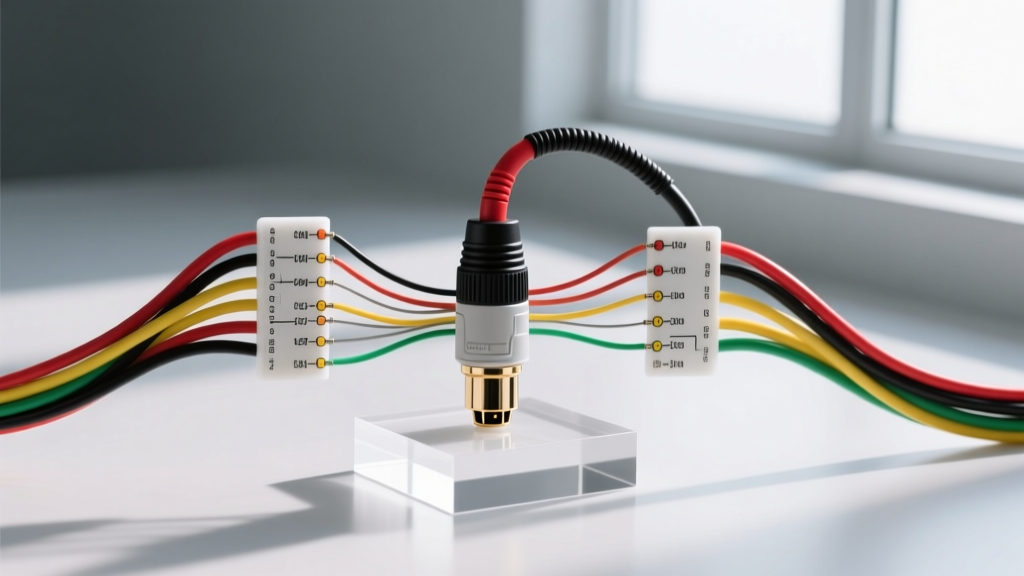
Introduction to XLR Connectors in Automotive Applications
While traditionally associated with studio audio and stage lighting, the XLR connector has become a critical component in advanced automotive electrical systems. High-end car audio Digital Signal Processors (DSPs) from brands like Audison and Helix utilize balanced XLR connections to transmit line-level audio without introducing alternator whine. In the off-road and motorsport sectors, 4-pin and 5-pin XLR configurations are the industry standard for heavy-duty intercom systems (such as PCI Race Radios and Rugged Radios) and telemetry sensor hubs. Understanding the correct wiring diagram for XLR connector applications in a vehicle requires navigating unique challenges, including severe Electromagnetic Interference (EMI), vibration, and moisture intrusion.
This product comparison and selection guide will break down the best automotive-grade XLR connectors, provide precise pinout wiring diagrams, and detail the wire gauge and shielding requirements necessary to maintain signal integrity in a 12V to 14.4V DC automotive environment.
Product Comparison: Selecting the Right XLR for Vehicles
Not all XLR connectors are built to survive the harsh environment of a vehicle trunk, door jamb, or engine bay. When selecting a connector for automotive harnesses, you must evaluate the latch mechanism, contact plating, and Ingress Protection (IP) rating. Below is a comparison of the top three brands used in custom automotive fabrication.
| Brand / Series | Best Automotive Application | Contact Plating | IP Rating | Latch Mechanism |
|---|---|---|---|---|
| Neutrik XX Series | High-End DSP Audio / Engine Bay Telemetry | Silver or Gold | IP40 (Standard) / IP65 (with sealing ring) | Sturdy die-cast latch with self-locking boot |
| Switchcraft Q-G Series | Interior Car Audio / Budget Intercoms | Silver | IP40 | Standard push-release latch |
| Amphenol AX Series | Military / Off-Road External Comms | Gold over Nickel | IP67 (Waterproof variants) | Heavy-duty push-button with dust cap |
Expert Selection Advice: For trunk-mounted DSP amplifiers, the Neutrik XX Series is the gold standard due to its superior strain relief boot, which prevents wire fatigue from subwoofer-induced vibrations. For external off-road intercoms routed through the firewall, Amphenol's IP67-rated waterproof connectors are mandatory to prevent green death (copper oxide corrosion) on the pins.
The Wiring Diagram for XLR Connector Configurations
The pinout of an XLR connector changes drastically depending on its automotive application. Below are the standard wiring diagrams and color codes used in professional automotive harness fabrication.
3-Pin XLR: Balanced Audio and DSP Integration
In automotive audio, a 3-pin XLR carries balanced analog audio from the head unit or DSP to the amplifier. Balanced signals use phase cancellation to reject EMI from ignition coils and alternators.
- Pin 1 (Shield / Ground): Bare drain wire. Critical Note: To prevent ground loops and alternator whine, Pin 1 must be tied to the chassis ground at the DSP (source) but left disconnected (lifted) at the amplifier (receive) end.
- Pin 2 (Hot / +): White or Red wire. Carries the positive phase audio signal.
- Pin 3 (Cold / -): Black or Blue wire. Carries the inverted phase audio signal.
4-Pin XLR: Motorsport Telemetry and Intercom Systems
Off-road racers and motorsport teams use 4-pin XLRs for headsets, combining microphone inputs and speaker outputs into a single robust connection.
- Pin 1 (Mic +): Red wire (22 AWG). Electret microphone positive bias.
- Pin 2 (Mic -): Black wire (22 AWG). Microphone ground/shield.
- Pin 3 (Speaker +): White wire (18 AWG). Headset speaker positive.
- Pin 4 (Speaker -): Green wire (18 AWG). Headset speaker negative.
5-Pin XLR: DMX Lighting and Stereo Comms
Used in custom off-road rigs for DMX-controlled LED rock lights and stereo intercom systems.
- Pin 1 (Common / GND): Black wire.
- Pin 2 (Data +): White wire (AES/EBU digital standard).
- Pin 3 (Data -): Blue wire.
- Pin 4 (Stereo Spk +): Red wire.
- Pin 5 (Stereo Spk -): Green wire.
Wire Gauge, Shielding, and SAE Standards
Selecting the correct wire is just as important as the connector itself. When routing cables through a vehicle chassis, the wire must resist heat, chemicals, and abrasion.
AWG Sizing by Application
- 22 AWG to 24 AWG: Ideal for balanced line-level audio and telemetry sensor data. Low current draw requires minimal copper, allowing for tighter bending radii in door jambs.
- 20 AWG: Used for AES/EBU digital audio and DMX lighting data lines.
- 18 AWG: Required for intercom speaker outputs and 12V power delivery to active sensors. Do not use 18 AWG for high-current amplifier power; reserve it strictly for signal and low-draw communication lines.
Shielding and SAE Compliance
For any analog signal in a vehicle, Shielded Twisted Pair (STP) wire is non-negotiable. The twisting of the positive and negative conductors (typically 2 to 4 twists per inch) rejects common-mode noise, while the aluminum foil shield blocks high-frequency EMI from spark plug wires. Ensure your wiring meets SAE J1128 standards for low-tension primary cable if routed near engine bay heat sources, or use TXL (thin-wall cross-linked) wire for high-temperature resistance up to 125°C. Always terminate the shield's drain wire using adhesive-lined heat shrink (such as 3M FP-301) to prevent moisture wicking into the connector barrel.
Real-World Failure Modes and Troubleshooting
Even with premium connectors and meticulous soldering, automotive XLR harnesses can fail. Use this decision tree to diagnose common issues in the field or on the dyno.
Symptom: High-Pitched Alternator Whine in Audio System
- Cause: Ground loop caused by Pin 1 (Shield) being grounded at both the DSP and the Amplifier, creating an antenna for the vehicle's charging system noise.
- Fix: Disconnect the shield wire from Pin 1 on the amplifier side. The shield should only be grounded at the source component. Verify the amplifier chassis ground is clean, bare metal with a torque spec of 10-15 Nm.
Symptom: Intermittent Data Dropouts in Telemetry / DMX Lighting
- Cause: Vibration-induced micro-fractures in the solder joints, or the use of standard 60/40 rosin-core solder which can crack under severe off-road harmonic frequencies.
- Fix: Desolder and re-terminate using silver-bearing solder (e.g., Kester 44) which offers higher tensile strength. Apply a dab of RTV silicone inside the Neutrik boot to act as a vibration dampener before screwing the housing back together.
Symptom: Corrosion / 'Green Death' on External Intercom Pins
- Cause: Moisture intrusion due to using standard IP40 connectors in exterior-mounted locations, leading to galvanic corrosion between the nickel shell and copper pins.
- Fix: Replace with IP67-rated Amphenol connectors. Apply Nyogel 760G dielectric grease to the pins before mating to displace moisture and prevent oxidation without interfering with the electrical contact.
Conclusion
Integrating XLR connectors into automotive wiring diagrams elevates the reliability and noise-rejection capabilities of any vehicle's electrical system. Whether you are configuring a 3-pin balanced audio harness for a competition car audio build, or wiring a 4-pin intercom for a desert racer, selecting the correct IP-rated connector and adhering to strict AWG and shielding standards is paramount. Always reference the specific pinout diagrams provided above, lift your shields on balanced audio runs, and utilize SAE-compliant TXL wire to ensure your harness outlasts the vehicle itself.