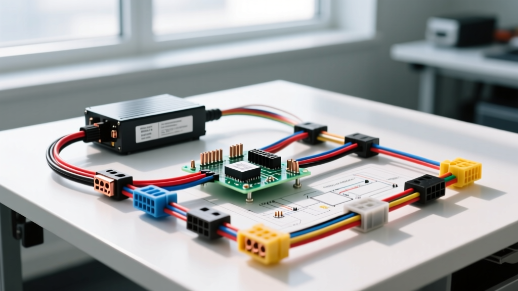
Why Bench Test an ECU Using a Computer Power Supply?
When diagnosing complex drivability issues, flashing custom calibrations, or rebuilding aftermarket engine management systems, removing the Powertrain Control Module (PCM) from the vehicle is often necessary. However, powering an automotive ECU on a workbench requires a stable, high-amperage DC source that can handle the sudden current draws of fuel injector drivers and ignition coils. This is where a standard ATX PC power supply becomes invaluable. By cross-referencing the wiring diagram for computer power supply units with OEM ECU pinouts, technicians can fabricate a safe, highly capable bench harness.
This guide provides a comprehensive cost and tool requirements analysis for building an ATX-to-ECU bench testing station, focusing on wire specifications, connector economics, and the fabrication tools required for professional-grade results.
The Core Reference: Wiring Diagram for Computer Power Supply (ATX 24-Pin)
Modern ATX power supplies utilize a 24-pin Molex Mini-Fit Jr. connector. Unlike automotive alternators that fluctuate between 13.2V and 14.8V, an ATX PSU provides a rock-solid 12.0V DC rail, which is ideal for bench-testing ECU logic boards without risking overvoltage damage to sensitive microprocessors. Below is the critical mapping of the ATX 24-pin wiring diagram to automotive ECU requirements.
| ATX Pin | Wire Color | Voltage | Automotive ECU Application | Recommended AWG |
|---|---|---|---|---|
| 10, 11, 12 | Yellow | +12V DC | ECU Main B+ Memory, Ignition Coils, Injector High-Side | 14 AWG (GXL) |
| 4, 6, 21, 22 | Red | +5V DC | Sensor 5V Reference (VREF), Logic Board Power | 18 AWG (TXL) |
| 1, 2, 13, 15 | Orange | +3.3V DC | Rarely used in auto; reserve for specific CAN-bus termination testing | 20 AWG |
| 3, 5, 7, 16-20, 23, 24 | Black | Ground (0V) | ECU Power Ground, Sensor Ground, Logic Ground | 14 AWG (GXL) |
| 16 | Green | PS_ON (Active Low) | Must be jumpered to Ground (Black) to turn the PSU on | 22 AWG |
| 8 | Gray | Power Good (+5V) | Can be wired to a bench LED to verify PSU stability before ECU connection | 22 AWG |
Reference: Intel ATX12V Power Supply Design Guidelines and standard Molex Mini-Fit Jr. specifications.
Cost Analysis: Building the Bench Harness
Building a reliable bench harness requires balancing initial tooling costs with the long-term durability of the materials. Cheap crimps and undersized wires lead to voltage drops that can cause an ECU to throw false internal codes (e.g., U0100 CAN bus timeouts or P0601 Internal Control Module Memory errors). Below is a detailed cost breakdown for a professional-grade setup.
Component & Material Breakdown
| Component | Specification | Estimated Cost | Notes |
|---|---|---|---|
| ATX Power Supply | 500W+ 80+ Bronze (EVGA/Corsair) | $45.00 - $65.00 | Ensure high amperage on the +12V rail (minimum 30A). |
| ATX Breakout Board | 24-Pin PCB with screw terminals | $12.00 - $18.00 | Eliminates the need to cut the main ATX harness. |
| Automotive Wire | SAE J1128 GXL / TXL (14, 16, 18 AWG) | $35.00 | Cross-linked polyethylene insulation handles soldering heat. |
| OEM ECU Pigtails | TE Connectivity / Deutsch DT (48-pin to 80-pin) | $40.00 - $85.00 | Model specific (e.g., GM E38, Ford CFI, Bosch ME7). |
| Circuit Protection | Inline MAXI/ATO fuse holders & 12V 30A Relays | $15.00 | Mandatory to protect the ECU from bench short-circuits. |
| Total Consumable Cost | $147.00 - $218.00 | Excludes fabrication tooling. | |
Wire insulation standards based on the SAE J1128 Low Tension Primary Cable Standard, which mandates specific wall thicknesses and temperature ratings for automotive environments.
Tool Requirements for Harness Fabrication
The most common point of failure in bench harnesses is a poorly crimped terminal. Automotive ECU connectors utilize micro-timers, Metri-Pack, or Deutsch DT contacts that require precise, ratcheting crimp dies. Using pliers or non-ratcheting tools will result in high-resistance connections that fail under the thermal cycling of injector driver testing.
Essential Fabrication Tooling
- Wire Strippers: Knipex MultiStrip 10 (Handles 24-10 AWG without nicking copper strands). Cost: ~$45.00
- Crimpers (OEM Connectors): TE Connectivity 58431-1 or equivalent ratcheting crimper for Metri-Pack 150/280 series. Cost: ~$120.00
- Crimpers (Deutsch DT): HDT-48-00 or IWISS SN-48B for 14-20 AWG solid barrel DT contacts. Cost: ~$35.00
- Heat Shrink & Torch: Dual-wall adhesive-lined heat shrink (3:1 ratio) and a butane micro-torch to seal splices against moisture and oxidation. Cost: ~$25.00
- Digital Multimeter (DMM): Fluke 87V or similar True-RMS meter for verifying voltage drop across the bench harness under load. Cost: ~$400.00
Tooling Investment Note: While the initial tooling cost exceeds $200, these tools are mandatory for any diagnostic technician or ECU calibration expert. Compromising on crimp tools leads to intermittent bench faults that mimic internal ECU failures.
Step-by-Step Integration: ATX to OEM ECU Connector
To illustrate the practical application of this setup, let us examine the integration of an ATX power supply to a widely tested automotive computer: the GM Gen IV E38 ECU (used in LS3, LS7, and L99 applications). The E38 utilizes two 80-pin TE Connectivity connectors (X1 and X2).
GM E38 Power & Ground Pinout Mapping
- Battery Positive (B+ Memory): Map ATX Yellow (+12V) to E38 Connector X1, Pins 1, 2, and 3. Run this through a 15A ATO fuse on the bench.
- Ignition Positive (Run/Crank): Map ATX Yellow (+12V) through a bench-mounted toggle switch and 30A relay to E38 Connector X1, Pin 9. This simulates the key-on event and wakes up the ECU logic.
- Main Grounds: Map ATX Black (Ground) to E38 Connector X1, Pins 73, 74, 75, and 76. Use 14 AWG GXL wire and a common bus bar to ensure zero voltage potential difference between the ECU grounds and the ATX ground rail.
- 5V Reference Check: Use the DMM to probe E38 Connector X2, Pin 29 (TPS 5V Ref). If the ATX Red (+5V) rail is properly isolated and the ECU is booting, you should read exactly 4.98V - 5.02V.
By utilizing a wiring diagram for computer power supply outputs alongside the GM service manual pinout, you can safely flash the ECU via the OBD-II port (using a bench-mounted OBD pigtail wired to CAN-H, CAN-L, and 12V) without risking vehicle-side electrical shorts.
Safety Protocols & Common Failure Modes
When merging PC hardware with automotive diagnostics, specific failure modes emerge that technicians must anticipate.
Diagnostic Decision Tree: Bench Harness Faults
- Symptom: ECU does not power on; ATX fan spins for 1 second and stops.
- Cause: Short circuit on the +12V or +5V rail triggering ATX Over-Current Protection (OCP).
- Fix: Check E38 X1 Pin 1 for a short to ground. Verify inline fuses are intact.
- Symptom: ECU powers on, but flashing software fails to communicate via CAN-bus.
- Cause: Ground loop or voltage drop on the CAN-bus ground reference.
- Fix: Ensure the OBD-II port Pin 4 (Chassis Ground) and Pin 5 (Signal Ground) are tied directly to the same ATX Black wire bus bar as the ECU grounds.
- Symptom: 5V Reference reads 4.2V under load.
- Cause: Undersized wire on the 5V rail or poor crimp on the TE Connectivity Metri-Pack terminal.
- Fix: Upgrade 5V feed to 16 AWG and re-crimp using a ratcheting die. Reference Haynes Automotive Electrical Repair Manuals for terminal retention force specs.
Conclusion
Building an ECU bench testing station using an ATX computer power supply is a highly cost-effective alternative to purchasing $2,000+ proprietary OEM breakout boxes. By strictly adhering to the wiring diagram for computer power supply configurations, utilizing SAE-rated automotive wire, and investing in proper ratcheting crimp tools, diagnostic experts can create a reliable, safe environment for ECU calibration, flashing, and component-level troubleshooting.