Introduction to Automotive Alarm Schematics
For many mobile electronics enthusiasts, looking at a security alarm wiring diagram for the first time feels like staring at a bowl of multicolored spaghetti. However, beneath the chaotic web of red, black, yellow, and green wires lies a highly logical system of inputs, outputs, and power distribution. Whether you are installing a basic Viper, Compustar, or Avital system, understanding the fundamentals of these schematics is the difference between a reliable security system and a vehicle that refuses to start.
This beginner-friendly guide breaks down the core circuits, standard wire color codes, AWG (American Wire Gauge) requirements, and relay logic necessary to safely and effectively install an aftermarket automotive security system. By mastering these fundamentals, you will be able to interpret almost any manufacturer's wiring schematic with confidence.
The Core Circuits: Decoding Standard Wire Colors
While OEM (Original Equipment Manufacturer) wire colors vary wildly between a 2015 Honda Civic and a 2020 Ford F-150, aftermarket alarm manufacturers adhere to a fairly standardized color-coding system for their main harnesses. Understanding this universal language is your first step in reading a security alarm wiring diagram.
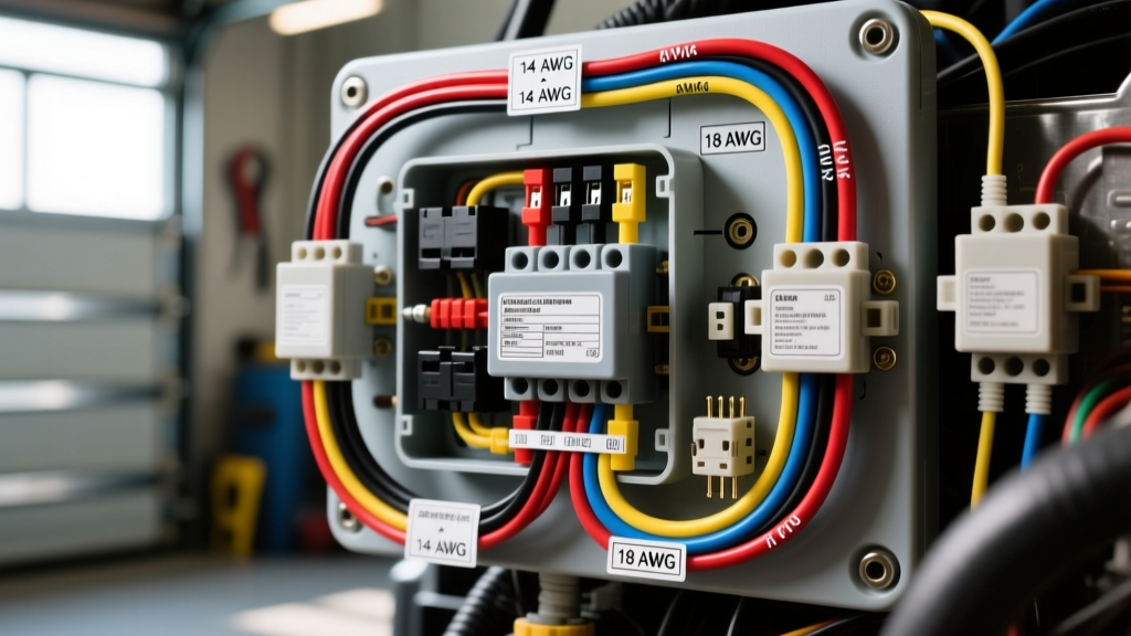
| Wire Color | Function | Typical AWG | Connection Point |
|---|---|---|---|
| Red | 12V Constant Battery Power | 10 AWG | Direct to Battery (+) or Main 12V Feed |
| Black | Chassis Ground | 10 AWG | Bare, unpainted metal bolt in kick panel |
| Yellow | Ignition 1 (Primary) | 18 AWG | Ignition switch harness (12V in Run/Start) |
| Green | Door Trigger Input | 18 AWG | OEM door pin switch or BCM data wire |
| Blue | Status / Trunk Release Output | 18 AWG | OEM trunk release relay coil |
| White | Light Flash / Parking Light Output | 16 AWG | OEM headlight switch or BCM (+) trigger |
Always cross-reference the specific manufacturer's guide, but memorizing these baseline colors will allow you to quickly identify the primary power and trigger harnesses before you even pick up a digital multimeter (DMM).
Power, Ground, and Ignition: The Lifelines
The most common failure point in amateur alarm installations is inadequate power and ground routing. According to SAE International standard J1128, automotive primary wire must withstand high under-hood temperatures and resist chemical degradation. When running your main Red (12V+) and Black (Ground) wires, you must use a minimum of 10 AWG Oxygen-Free Copper (OFC) wire.
The 18-Inch Fuse Rule
Your main 12V constant power wire must be fused within 18 inches of the vehicle's battery positive terminal. A 15-Amp or 20-Amp inline AGU/ATO fuse is standard for most alarm brain modules. If a short circuit occurs in the wiring harness, this fuse prevents the wire from melting and starting an electrical fire. Never bypass this fuse, and never use a higher amperage fuse than specified in the diagram.
Establishing a True Ground
Do not ground your alarm module to a painted surface or a thin sheet-metal screw. Locate a thick, unpainted structural bolt in the driver's side kick panel or under the dash. Sand away any paint or rust, attach a high-quality ring terminal, and secure it tightly. A poor ground will cause the alarm module to reboot randomly, trigger false siren alarms, or fail to lock the doors.
Understanding the Starter Kill Relay Diagram
A true security system does more than make noise; it prevents the vehicle from being driven away. This is achieved via a starter interrupt circuit using an SPDT (Single Pole, Double Throw) automotive relay. Your security alarm wiring diagram will usually include a small schematic for this 5-pin relay. Here is how the standard ISO mini relay pinout functions:
- Pin 86 (Coil +): Connected to the alarm module's starter kill output wire (usually Orange or Purple). Receives 12V+ when the alarm is triggered.
- Pin 85 (Coil -): Connected to a solid chassis ground.
- Pin 30 (Common): Connected to the OEM starter wire coming from the ignition switch.
- Pin 87a (Normally Closed): Connected to the OEM starter wire going to the starter solenoid. Allows the car to start normally when the alarm is disarmed.
- Pin 87 (Normally Open): Left empty or connected to ground (for safety). When the alarm triggers, the relay switches from 87a to 87, breaking the starter circuit.
Pro Tip: Always use 12 AWG wire for pins 30, 87, and 87a. The starter solenoid draws significant amperage, and using thin 18 AWG wire on the interrupt loop will result in a voltage drop, causing the engine to crank sluggishly or not at all.
Door Triggers: Positive vs. Negative Detection
The Green wire on your alarm harness is the universal door trigger input, but how it behaves depends on the vehicle's age and manufacturer. Reading the vehicle-specific security alarm wiring diagram is critical here to avoid shorting out the Body Control Module (BCM).
Negative Door Triggers (Most Modern Vehicles)
In most modern vehicles (Honda, Toyota, GM, Ford post-2005), the door pin switches provide a ground (-) signal when the door is opened. The alarm module's green wire is designed to detect this drop to 0V. You will connect the green wire to the OEM door trigger wire at the kick panel or BCM.
Positive Door Triggers (Older Vehicles)
Older Fords, Chrysler products, and some European vehicles use a 12V (+) positive trigger. When the door opens, 12V is sent through the dome light circuit. If your alarm module supports it, you must move an internal jumper or programming menu option to "Positive Door Trigger." If the module does not support positive triggers natively, you must use a relay to invert the positive signal into a negative ground signal for the alarm brain.
Professional Splicing vs. Amateur T-Taps
The Mobile Electronics Certification Program (MECP) strictly advises against the use of "T-Taps" or "Scotch-Loks" for permanent automotive electrical installations. While they are tempting for beginners because they require no wire stripping, they pierce the wire insulation and leave the copper strands exposed to moisture, leading to rapid galvanic corrosion and eventual failure.
The Military Splice Method
For a reliable connection, use the "Military Splice" (or Western Union splice) method:
- Strip 1/2 inch of insulation from both the OEM wire and the alarm wire using high-quality wire strippers.
- Twist the exposed copper strands together tightly.
- Solder the connection using rosin-core solder and a temperature-controlled iron.
- Cover the joint with dual-wall, adhesive-lined heat shrink tubing to seal out moisture and provide strain relief.
For high-current circuits like the starter interrupt or power windows, use crimp connectors with a proper ratcheting crimp tool, followed by heat shrink.
Troubleshooting the "No-Arm" Condition
One of the most frustrating experiences for a beginner is finishing the installation, pressing the lock button on the remote, and hearing a series of chirps indicating the alarm refuses to arm. This is almost always caused by an active trigger. Use this diagnostic checklist:
- Door Trigger Active: Check if the dome light is on. If the green wire is receiving a constant ground or 12V+ due to a misidentified wire, the brain thinks a door is open.
- Hood/Trunk Pin Switches: Verify that your aftermarket hood pin switch is not being constantly depressed by a rubber stopper, or that the trunk trigger wire isn't pinched in the hinge.
- Ignition Wire Cross-Talk: Ensure your yellow ignition wire is not back-feeding voltage from an accessory circuit. Use your DMM to verify the yellow wire reads exactly 0V when the key is out of the ignition.
- Shock Sensor Sensitivity: If the vehicle is parked near a busy road or in a windy area, an overly sensitive shock sensor will trigger the alarm immediately after arming. Turn the sensitivity dial down and re-test.
Final Thoughts on Diagram Interpretation
Mastering a security alarm wiring diagram is about understanding the flow of electricity from the battery, through the module's logic board, and out to the vehicle's actuators. Always rely on a high-quality Digital Multimeter to verify every single OEM wire before making a connection. Never trust a generic wire color chart found on an internet forum; always verify with your own testing equipment. For comprehensive vehicle-specific wiring diagrams and pinouts, resources like the12volt.com remain invaluable references for both beginners and seasoned MECP-certified installers. Take your time, route your wires safely away from moving pedals and hot exhaust components, and prioritize soldered connections for a security system that will last the lifetime of the vehicle.