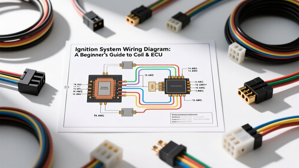
Introduction to the Ignition System Wiring Diagram
For any automotive technician or DIY enthusiast, the ignition system wiring diagram is the foundational map for diagnosing misfires, no-start conditions, and performance issues. Modern vehicles have largely abandoned mechanical distributors in favor of Coil-On-Plug (COP) or Coil-Near-Plug (CNP) configurations. While this eliminates moving parts, it vastly increases the complexity of the electrical schematics. A beginner might look at a factory service manual and see a chaotic web of lines, but once you understand the core logic of primary power, ground references, and Powertrain Control Module (PCM) trigger signals, the diagram becomes a straightforward diagnostic tool.
This guide breaks down the fundamental anatomy of ignition schematics, teaching you how to trace circuits, identify wire gauges, and interpret connector pinouts with confidence.
Core Components in an Ignition Schematic
Before tracing a wire, you must recognize the primary actors in the ignition circuit. Every modern ignition system wiring diagram will feature these critical nodes:
- The Power Source: Usually fed from the ignition switch or a dedicated PCM-controlled relay. This provides the raw 12V battery voltage required to saturate the coil.
- The Ignition Coil (Primary & Secondary): The coil is a transformer. The diagram will show the primary circuit (low voltage, high current) but will rarely detail the secondary circuit (high voltage, low current) beyond the coil boot, as secondary voltage jumps the spark plug gap rather than traveling through standard chassis wiring.
- The PCM/ECU Driver: The computer controls the spark event by grounding the primary circuit. When the PCM internal transistor opens, the magnetic field collapses, inducing the high-voltage spark.
- Position Sensors: The Crankshaft Position (CKP) and Camshaft Position (CMP) sensors are not physically wired to the coils, but their signals dictate when the PCM fires the coil. Schematics often group these sensor inputs on the same PCM connector pages as the coil outputs.
Decoding the Diagram: Wire Colors, AWG, and Symbols
Automotive wiring diagrams use standardized color codes and line weights to indicate wire size and function. According to SAE J1128 standards for low-tension primary cables, wire gauge (AWG) is selected based on current draw and circuit length to prevent voltage drop.
Standard Ignition Circuit Wire Specifications
| Circuit Function | Typical AWG Size | Common OEM Wire Color | Current / Voltage Profile |
|---|---|---|---|
| Primary Power (B+) | 14 AWG | Pink or Red | 12V - 14.4V / Up to 10A per coil |
| Primary Ground | 16 AWG | Black | 0V / Handles primary coil saturation current |
| PCM Trigger (Control) | 18 or 20 AWG | White, Blue, or Yellow | 5V Square Wave / Milliamp draw |
| Tachometer / Feedback | 18 or 20 AWG | Purple or Green | Low Voltage Pulse / Signal to Gauge Cluster |
Note: Wire colors vary heavily by manufacturer. Always rely on the legend in your specific factory service manual rather than memorizing colors.
Reading Connector Pinouts and Cavity Numbers
One of the most common beginner mistakes when using an ignition system wiring diagram is misidentifying connector cavities. Diagrams typically show connectors from the mating face (the side you plug into), not the wire side.
If a diagram labels a 4-pin coil connector with cavities A, B, C, and D, you must look at the front of the disconnected coil harness plug. Most OEM connectors feature microscopic letters molded into the plastic shell next to each terminal cavity. If you probe from the back (wire side), your pin A and B readings will be reversed, leading to false diagnostic conclusions.
Step-by-Step: Tracing a GM LS-Series COP Circuit
Let us apply these fundamentals to a real-world scenario. The General Motors LS V8 engine family uses a highly standardized 4-pin Coil-On-Plug design. By analyzing the ignition system wiring diagram for an LS1/LS6 or Gen III truck, we can map the exact circuit.
The 4-Pin Coil Connector Breakdown
- Pin A (Power): 14 AWG Pink wire. Fed from the IGN 1 relay. This wire must show battery voltage with the key in the 'Run' or 'Crank' position.
- Pin B (Ground): 16 AWG Black wire. Routes directly to the engine block ground stud (e.g., G102). This is a dedicated, clean ground, not a daisy-chained chassis ground.
- Pin C (PCM Trigger): 18 AWG White wire. Connects directly to the PCM. The PCM provides a 5V reference and pulls this circuit to ground to charge the coil, then opens the circuit to fire the spark.
- Pin D (Feedback/Tach): 18 AWG Purple wire. Sends a low-voltage pulse back to the PCM or instrument cluster to verify the coil fired and to drive the tachometer needle.
Understanding Dwell Time on the Schematic
When analyzing the PCM trigger wire (Pin C) with an oscilloscope, you will see a square wave. The 'on' time (when the PCM grounds the circuit) is called dwell time. As engine RPM increases, the time between sparks decreases. The PCM dynamically adjusts dwell time based on battery voltage; if the alternator is failing and voltage drops to 11V, the PCM will increase dwell time to ensure the primary coil still reaches full magnetic saturation. A wiring diagram will not show dwell time, but understanding this PCM logic explains why a weak battery can cause high-RPM misfires even if the coil itself is mechanically sound.
Common Failure Modes and Multimeter Testing
Armed with your ignition system wiring diagram, you can systematically isolate failures. As detailed in Autoshop 101's Automotive Electrical Diagnostics guides, never guess—trace the circuit.
Diagnostic Decision Tree for a Single-Cylinder Misfire
- Verify Primary Power: Set your multimeter to DC Volts. Back-probe Pin A (Power) with the key ON. You should read within 0.5V of battery voltage. If you read 0V, consult the diagram to trace the wire back to the ignition relay or check for a blown fuse.
- Perform a Voltage Drop Test on Ground: Do not just check for continuity. Set the multimeter to DC Volts. Place the red lead on the battery positive terminal and the black lead on Pin B (Ground) at the coil harness. Crank the engine. A reading above 0.2V indicates high resistance in the ground wire or engine block grounding strap.
- Check the Control Circuit (PCM Trigger): A standard multimeter will only show an average voltage (around 1.5V to 2.5V) on Pin C because it cannot read the rapid 5V square wave fast enough. To properly test this, use a NOID light or an oscilloscope. If the NOID light flashes while cranking, the PCM and the 18 AWG trigger wire are intact, pointing to a failed ignition coil or spark plug.
- Test Coil Primary Resistance: Disconnect the coil. Measure resistance across the primary internal terminals (usually the power and trigger pins). According to Bosch Mobility Solutions technical documentation, primary resistance should typically fall between 0.5 and 2.0 ohms. An open reading (OL) confirms an internal coil break.
Safety Warning: The Secondary Circuit
While the wiring diagram focuses on the primary 12V and 5V circuits, never forget the secondary circuit. Modern COP systems generate between 30,000 and 50,000 volts. Never attempt to test the secondary output by pulling a plug wire or coil boot off while the engine is cranking. This not only poses a severe shock hazard but will instantly destroy the PCM's internal driver transistor due to the lack of a ground path for the high-voltage arc, turning a $40 coil replacement into a $1,000 computer replacement.
Summary
Mastering the ignition system wiring diagram requires shifting your perspective from viewing wires as mere cables to understanding them as specific pathways for power, ground, and logic. By identifying the primary power feed, verifying dedicated grounds, and properly interpreting the PCM's low-current trigger signals, you can diagnose complex drivability issues with surgical precision. Always keep your factory service manual open, respect the AWG ratings, and let the schematic guide your multimeter probes.