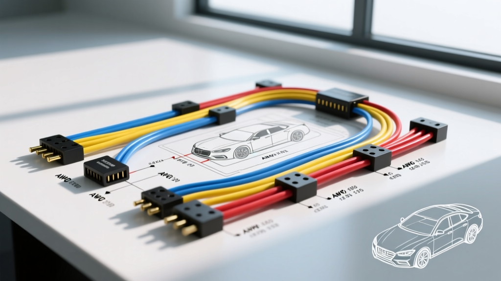
Project Overview: Integrating Modern Prox Sensors into Classic Platforms
Retrofitting a classic truck, vintage SUV, or early-2000s platform with modern ultrasonic parking assist is one of the highest-value modification projects you can undertake. However, simply zip-tying a control module under the dash and tapping into the reverse light circuit often results in phantom warnings, EMI interference, and blown fuses. A proper prox sensor wiring diagram must account for signal shielding, isolated trigger circuits, and precise pinout configurations to ensure OEM-level reliability.
This guide provides a comprehensive wiring schematic and installation protocol for a 4-channel (rear) or 8-channel (front and rear) ultrasonic proximity sensor upgrade. We will cover the exact AWG requirements, relay isolation logic for front-sensor triggers, and critical grounding techniques required to defeat the electromagnetic interference (EMI) generated by aftermarket ignition systems and high-output alternators.
Core System Architecture & Component List
Before cutting into your vehicle's harness, understand the architecture of a high-end aftermarket prox sensor kit. Unlike cheap eBay units that multiplex signals over a single unshielded wire, professional-grade systems utilize dedicated circuits for each 25mm ultrasonic transducer.
- Ultrasonic Transducers (Sensors): 25.5mm diameter, 3-pin waterproof connectors (Signal, 5V VCC, Ground).
- Main Control Module: Processes time-of-flight (ToF) acoustic echoes. Requires a clean chassis ground and isolated +12V power.
- HMI / Display: CAN-bus or analog PWM output to a dash-mounted LED array or HUD.
- Trigger Circuitry: Diodes and micro-relays to prevent backfeeding into the vehicle's BCM (Body Control Module) or reverse lamp circuits.
The Custom Prox Sensor Wiring Diagram & Pinout
The heart of this modification is the main control module harness. Below is the definitive pinout for a professional-grade 16-pin prox sensor control module. When referencing your prox sensor wiring diagram, ensure your connector matches this standard configuration to prevent shorting the 5V sensor reference voltage to a 12V source.
| Pin | Wire Color | Function | AWG | Connection Point |
|---|---|---|---|---|
| 1 | Red | +12V Constant (Battery) | 16 AWG | Fused direct to battery (+) |
| 2 | Yellow | +12V Switched (Ignition) | 18 AWG | Ignition run/start circuit |
| 3 | Black | Main Chassis Ground | 16 AWG | Clean, bare metal chassis point |
| 4 | Green | Rear Trigger (+12V) | 18 AWG | Reverse lamp circuit (via diode) |
| 5 | Blue | Front Trigger (+12V) | 18 AWG | Manual switch or VSS relay |
| 6 | White/Green | CAN-H (Optional HUD) | 22 AWG | OBD-II Pin 6 or BCM CAN-H |
| 7 | White/Blue | CAN-L (Optional HUD) | 22 AWG | OBD-II Pin 14 or BCM CAN-L |
| 8 | Orange | Display PWM Signal | 22 AWG | Dash LED array |
| 9 | Purple | Buzzer +12V Output | 20 AWG | Interior piezo buzzer (+) |
| 10 | Brown | Mute / Radio Dim | 22 AWG | OEM Radio Mute pin (optional) |
| 11-16 | Various | Sensor Diagnostic / Temp | 22 AWG | Reserved / N/C |
Note: The individual sensor pigtails (Sensors 1 through 4) plug into a separate sealed 12-pin Deutsch DT connector on the module. Never splice the 5V VCC or Signal wires of the ultrasonic transducers; they must remain continuous from the sensor head to the module to maintain signal integrity.
Power, Ground, and Trigger Circuit Integration
The most common failure point in a prox sensor upgrade is the trigger circuit. If you are installing both front and rear sensors, you must isolate the triggers. The rear sensors are triggered by the reverse light circuit. However, modern vehicles use PWM (Pulse Width Modulation) for lighting or have sensitive BCMs that will throw a 'bulb out' error if you tap directly into the reverse wire to power a module.
Diode Isolation for Rear Triggers
Always use a 1N5408 (3A) diode on the rear trigger wire (Pin 4). Connect the anode to the vehicle's reverse light wire and the cathode to the prox sensor module. This prevents the module's internal capacitors from backfeeding voltage into the BCM when the vehicle is shifted out of reverse, which can cause the backup cameras or BCM to stay awake and drain the battery.
Front Sensor Relay Logic
Front proximity sensors should only activate at low speeds (under 10 MPH) or via a manual toggle. Tapping into a speedometer signal (VSS) requires a signal conditioning relay. For a simpler, highly reliable modification, use a standard Bosch-style 4-pin micro relay (Part #0332014150) wired to a momentary toggle switch on the dash:
- Relay Pin 30: +12V Switched (Ignition)
- Relay Pin 87: To Prox Module Pin 5 (Front Trigger)
- Relay Pin 86: Dash Momentary Switch
- Relay Pin 85: Chassis Ground
This ensures the prox sensor module receives a clean, solid +12V signal without drawing current directly through a small dash switch.
Wire Gauge, Shielding, and Routing Specifications
Ultrasonic prox sensors operate by emitting a 48 kHz acoustic pulse and measuring the electrical echo. The signal wire carrying this echo back to the module is highly susceptible to EMI. According to SAE J1113 standards for Electromagnetic Compatibility, unshielded signal wires routed near high-voltage ignition components will act as antennas, inducing false 'phantom obstacle' warnings.
| Circuit Type | Recommended Wire | Routing Rules |
|---|---|---|
| Main Power / Ground | 16 AWG TXL (Cross-linked) | Route away from exhaust; use ring terminals with star washers. |
| Trigger / Relay | 18 AWG GXL | Can be bundled with OEM chassis harness. |
| Sensor Signal / VCC | 22 AWG Shielded Twisted Pair (STP) | MUST NOT route parallel to spark plug wires or MSD ignition boxes. |
| CAN-Bus (if used) | 22 AWG Shielded Twisted Pair | Maintain OEM CAN-bus twist rate (1 twist per inch). |
The Shield Grounding Rule
When using shielded wire for the prox sensor pigtails, the metallic drain wire (shield) must be grounded at the control module end only. If you ground the shield at the bumper/sensor end as well, you create a ground loop. The vehicle's chassis will act as a conductor for alternator whine and starter motor noise, directly injecting it into the sensor's signal wire. Solder the drain wire to Pin 11 (Sensor Ground Reference) at the module, and wrap the bumper end in heat shrink.
Real-World Troubleshooting: EMI and Ground Loops
Even with a flawless prox sensor wiring diagram, physical installation variables can cause system faults. Here is the diagnostic decision tree for common upgrade issues:
Symptom: All sensors read '0.0m' or max distance constantly
Cause: Loss of 5V VCC reference or main ground failure.
Fix: Check Pin 3 (Ground) for voltage drop under load. A poor ground will cause the module's internal 5V voltage regulator to sag to 3.2V, which is below the threshold required to power the ultrasonic transducers. Use a digital multimeter to verify < 0.1V drop between the module ground pin and the battery negative terminal.
Symptom: Phantom warnings (beeping) when no obstacle is present
Cause: EMI interference or sensor angle misalignment.
Fix: First, check the physical mounting. As noted in Bosch Mobility Solutions technical documentation, ultrasonic sensors have a conical detection field (typically 120 degrees horizontal, 60 degrees vertical). If the sensor is mounted pointing slightly downward toward the ground or inward toward a protruding bumper bracket, it will detect the vehicle's own bodywork. Second, if angles are correct, use an oscilloscope on the signal wire to check for high-frequency noise induced by aftermarket CDI/ignition boxes. Relocate the module away from the firewall and ensure STP shielding is intact.
Symptom: System stays on after shifting out of Reverse
Cause: Missing isolation diode or backfeeding from a dual-filament bulb socket.
Fix: Install the 1N5408 diode on the Green trigger wire. If the issue persists, the vehicle's tail light socket may have a melted divider between the brake and reverse circuits, causing 12V to leak into the reverse circuit when the brakes are applied. Repair the socket and add a secondary 12V 4-pin relay to physically break the trigger circuit.
Final Integration and Testing
Before buttoning up the bumper and interior trim, perform a 'bench test' by plugging all sensors into the module and laying them on a workbench facing an open area. Power the module and verify the HMI display initializes without fault codes. For deeper integration into modern vehicles, consult Painless Performance Wiring guides for specific BCM pinouts if you intend to use the OEM radio mute feature (Pin 10) to silence the stereo during parking maneuvers. A properly executed prox sensor wiring diagram and harness build will yield a seamless, factory-appearing upgrade that dramatically improves daily drivability and low-speed maneuverability.