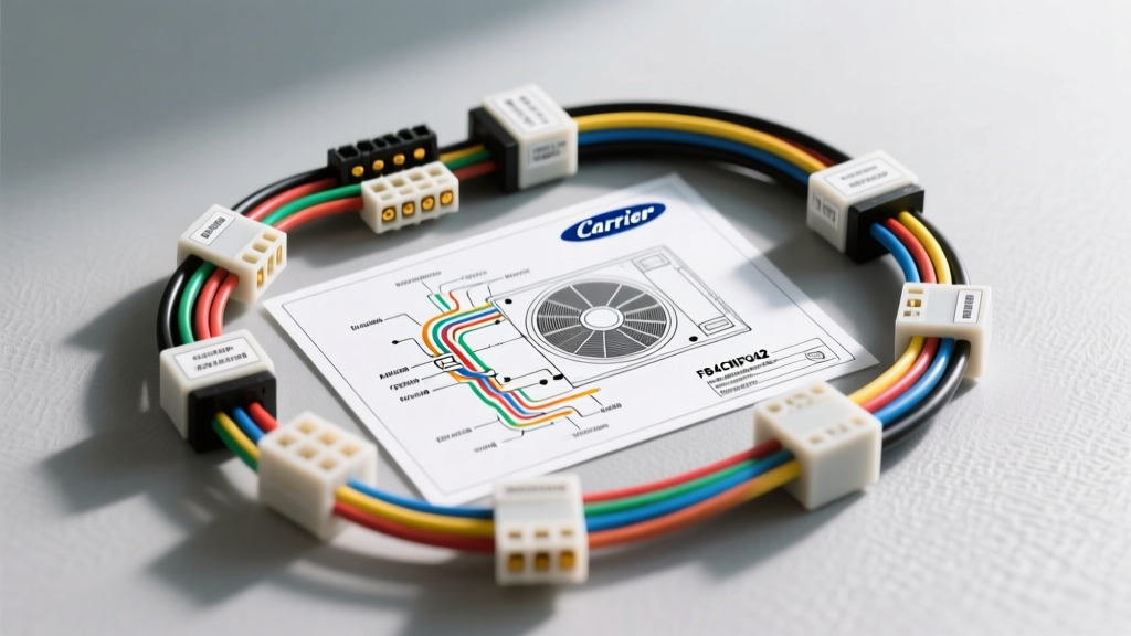
Integrating the Carrier FB4CNF042 into Mobile & Expedition Platforms
When outfitting large-scale expedition RVs, skoolie conversions, or heavy-duty mobile command centers, standard 13,500 BTU rooftop air conditioners rarely provide sufficient climate control. For these high-demand builds, integrators frequently turn to residential and light-commercial fan coil units. The Carrier FB4CNF042, a robust 3.5-ton (42,000 BTU) air handler, is a popular choice due to its high airflow capacity and durable blower assembly. However, adapting a stationary 208/230V or 120V HVAC system to a mobile DC-to-AC electrical architecture requires precise planning. This practical how-to guide and accompanying Carrier FB4CNF042 wiring diagram PDF breakdown will walk you through the exact pinouts, wire gauges, and inverter configurations required to safely run this unit off a vehicle-based lithium battery bank.
Decoding the Carrier FB4CNF042 Wiring Diagram PDF
The factory Carrier FB4CNF042 wiring diagram PDF typically outlines two distinct electrical circuits: the high-voltage blower motor supply and the low-voltage 24V AC control circuit. In a mobile environment, your primary challenge is generating clean AC power from a 12V, 24V, or 48V DC battery bank to satisfy both circuits simultaneously.
High-Voltage Blower Motor Circuit
Depending on the specific sub-model and manufacturing year, the FB4CNF042 blower motor may be a 120V PSC (Permanent Split Capacitor) motor or a 208/230V ECM (Electronically Commotated Motor). For expedition vehicles, the 120V configuration is heavily preferred. If your unit requires 208/230V, you must utilize a split-phase 120/240V inverter stack (such as dual Victron Quattros) or a high-capacity 120V-to-240V autotransformer. The high-voltage terminal block requires a dedicated 30A double-pole breaker (for 240V) or a 30A single-pole breaker (for 120V). You must use a minimum of 10 AWG THHN wire routed through flexible metallic conduit (FMC) or a heavy-duty SOOW portable power cord to isolate vibration from the vehicle chassis.
Low-Voltage Control Board (24V AC)
The control board requires a 24V AC power supply to energize the blower relay, electric heat strips (if equipped), and communicate with the thermostat. In a mobile build, this 24V AC is typically stepped down from the inverter's 120V AC output using a dedicated 40VA 120V-to-24V transformer, or sourced directly from an RV-specific HVAC control module. Never attempt to step down 12V DC to 24V AC using a cheap DC-DC converter; the control board requires a true AC sine wave to properly sequence the contactor and blower relays.
Vehicle-Specific Power Architecture & Wire Sizing
Sizing your DC-side wiring is critical. The Carrier FB4CNF042 blower can draw up to 12-15 Amps at 120V under full load, translating to roughly 1,800 Watts. When accounting for inverter inefficiency (typically 85-90%) and the initial locked-rotor amperage (LRA) surge of the motor, your DC cabling must handle massive transient currents. Below is the required AWG sizing for the DC battery-to-inverter runs based on NFPA 1192 (Standard on Recreational Vehicles) and SAE guidelines.
| Circuit Segment | Voltage / Current | Recommended AWG | Overcurrent Protection | Insulation Type |
|---|---|---|---|---|
| Battery Bank to Inverter (12V System) | 12V DC / 180A+ Surge | 2/0 AWG Welding Cable | 250A ANL / Class T Fuse | EPDM / Fine-stranded copper |
| Battery Bank to Inverter (24V System) | 24V DC / 90A+ Surge | 1/0 AWG Welding Cable | 150A ANL Fuse | EPDM / Fine-stranded copper |
| Inverter AC Out to HVAC Disconnect | 120V AC / 20A Continuous | 10 AWG THHN or 10/3 SOOW | 30A Single-Pole Breaker | THHN in FMC or SOOW Jacket |
| Transformer to 24V Control Board | 24V AC / 1.5A Max | 18 AWG Solid Core | 3A Inline ATC Fuse | Thermostat Wire (18/2) |
Step-by-Step Installation & Termination Guide
- Mount the Air Handler & Isolate Vibration: Secure the FB4CNF042 to the vehicle subfloor using M8 stainless steel bolts. Crucially, place 1/2-inch neoprene vibration isolation pads between the unit and the chassis to prevent road harmonics from transferring into the ductwork and cracking the internal sheet metal.
- Run the High-Voltage AC Feed: Route your 10/3 SOOW cable from the inverter's AC distribution panel to a local HVAC disconnect box mounted within 3 feet of the Carrier unit. Terminate the Black (L1), White (Neutral), and Green (Ground) wires. Torque all terminal block screws to 15 in-lbs to prevent arcing under vehicular vibration.
- Install the 24V Step-Down Transformer: Mount a 40VA 120V-to-24V transformer inside the air handler's control compartment. Wire the 120V primary side to a dedicated 5A breaker on your AC panel. Wire the 24V secondary side to the control board's 'C' (Common) and 'R' (Hot) terminals.
- Wire the Thermostat Controls: Run an 18/5 shielded thermostat cable from your mobile command center's living space to the FB4CNF042 control board. Shielded cable is mandatory in vehicles to prevent electromagnetic interference (EMI) from the inverter and alternator from causing ghost-signals to the HVAC relays, a common issue documented in SAE J1113 EMI testing standards.
- Perform the Pre-Flight Test: Before sealing the ductwork, energize the inverter. Measure the AC voltage at the unit's terminal block (should be 115V-120V). Measure the 24V AC at the control board. Trigger the 'G' (Fan) circuit at the thermostat and verify the blower spins up smoothly without abnormal humming.
Thermostat to Control Board Pinout Reference
Correctly mapping the thermostat wires to the Carrier FB4CNF042 control board is essential for proper staging. If your build includes auxiliary electric heat strips, ensure the 'W' terminal is wired through a high-amperage contactor, as the control board's internal relays are not rated for the 30A+ draw of mobile electric heat strips.
| Terminal Label | Wire Color (Standard 18/5) | Function | Mobile Integration Notes |
|---|---|---|---|
| R | Red | 24V AC Hot | Power from secondary side of step-down transformer. |
| C | Blue or Black | 24V AC Common | Completes the control circuit. Do not confuse with DC ground. |
| G | Green | Indoor Blower Fan | Energizes the main blower relay for fan-only circulation. |
| Y1 | Yellow | Compressor Stage 1 | Routes to the external condenser contactor coil. |
| W1 | White | Heat Stage 1 | Use an external 40A contactor for electric heat strips. |
Real-World Troubleshooting: Inverter Harmonics & ECM Motors
The most frequent failure mode when installing the Carrier FB4CNF042 in an RV or expedition truck is blower motor failure or control board resets. This is almost exclusively caused by using a Modified Sine Wave (MSW) inverter. ECM motors and modern HVAC control boards require a Pure Sine Wave (PSW) output. MSW inverters introduce severe Total Harmonic Distortion (THD), which causes the ECM motor's internal rectifier to overheat and the control board's microprocessor to lock up.
If the blower motor hums but fails to start, verify your inverter's THD rating; it must be under 5%. Additionally, check the DC-side voltage drop. If your 2/0 AWG battery cables are too long or improperly crimped, the voltage at the inverter may drop below 10.5V during the motor's startup surge, triggering the inverter's Low Voltage Cutoff (LVC) and instantly killing power to the HVAC unit. Always use a hydraulic crimper for all DC lugs and seal them with adhesive-lined heat shrink to prevent moisture ingress and corrosion, ensuring reliable operation in harsh off-grid environments.
For further reference on OEM control board diagnostics and factory error codes, always consult the official Carrier HVAC technical literature portal to match your specific serial number's wiring schematic.