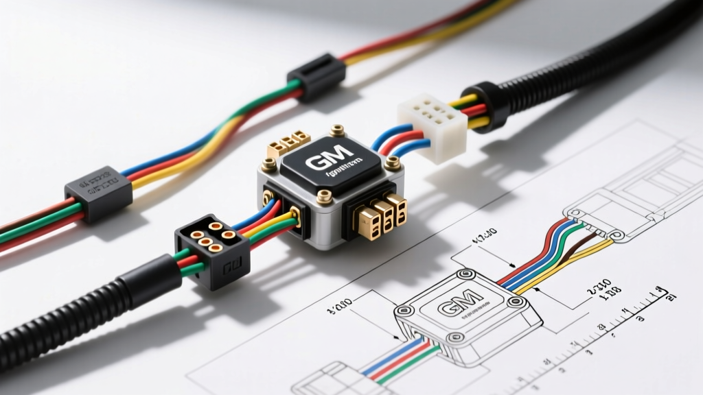
Introduction to the GM HEI System
When General Motors introduced the High Energy Ignition (HEI) system in 1974, it revolutionized automotive electrical systems. By integrating the ignition coil and electronic control module directly into the distributor cap, GM eliminated the need for external ballast resistors, points, and condensers. For classic car restorers and beginner mechanics, understanding a standard HEI ignition wiring diagram is one of the most valuable skills you can develop. Unlike modern coil-on-plug systems that require complex ECU mapping, the HEI system relies on straightforward analog electronics and basic 12-volt DC principles.
This beginner-friendly guide breaks down the fundamental wiring architecture of the GM HEI distributor. We will cover the 4-pin ignition control module (ICM) pinouts, proper wire gauge selection, thermal management, and the critical retrofit procedures required when swapping from a traditional points-style ignition to an HEI setup.
Core Components of the HEI Distributor
Before routing any wires, you must understand the internal architecture of the distributor. The HEI system relies on a magnetic pickup coil and a star-shaped reluctor wheel to trigger the spark. As the reluctor teeth pass the magnetic pickup, an alternating current (AC) voltage signal is generated. This signal is sent to the Ignition Control Module (ICM), which interprets the signal and switches the primary side of the ignition coil to ground, collapsing the magnetic field and sending high voltage to the spark plugs.
- Pickup Coil (Stator): Generates the trigger signal.
- Reluctor Wheel: Rotates with the distributor shaft to dictate timing.
- Ignition Control Module (ICM): The solid-state brain that switches the coil.
- Ignition Coil: Usually mounted directly in the center of the distributor cap (cap-mounted) to eliminate secondary voltage loss.
Translating the HEI Ignition Wiring Diagram
A standard GM HEI ignition wiring diagram is remarkably simple compared to modern engine harnesses. The entire system can be powered and controlled using just a few primary wires. The heart of the external wiring interface is the 4-pin connector located on the edge of the ignition control module.
The 4-Pin Ignition Control Module (ICM) Pinout
Understanding the function of each pin on the ICM is critical for proper operation and troubleshooting. Below is the standard pinout configuration for a Delco-Remy 4-pin HEI module:
| Pin Label | Wire Color (OEM) | Function & Connection | AWG Requirement |
|---|---|---|---|
| BATT | Red | Switched 12V power source from ignition switch. Must be full battery voltage (no resistance). | 12 AWG |
| TACH | White / Black | Connects to the negative (-) terminal of the ignition coil and provides the trigger signal for an aftermarket tachometer. | 14 AWG |
| GND | Black | Grounds the internal circuitry of the module to the aluminum distributor housing. | 12 AWG |
| W | Green | Often used for early computer control timing retard or diagnostic test ports. In basic carbureted retrofits, this pin is typically left unconnected or capped. | N/A |
Source Reference: For deeper diagnostics on module switching times, refer to the Delphi Technologies Service Data archives, which inherited the original Delco Remy engineering specifications.
Step-by-Step Wiring Execution for Beginners
When executing your HEI ignition wiring diagram, the order of operations and the quality of your terminations matter just as much as the routing. Follow these steps to ensure a reliable, spark-loss-free installation.
Step 1: Establishing a Clean 12V Power Source
The BATT terminal requires a clean, switched 12V source. This means the wire should only have power when the ignition key is in the 'RUN' and 'START' positions. Run a 12 AWG primary wire from a fused ignition source in your fuse block or directly from the ignition switch's IGN terminal. Always use a 20-amp inline fuse or a dedicated fuse block slot to protect the circuit from a dead short.
Step 2: Grounding the Module and Distributor
The HEI module draws significant current (up to 8 amps during dwell). A poor ground will cause the module to overheat and fail prematurely. The GND pin on the module grounds internally to the distributor base. Therefore, the distributor housing itself must be perfectly grounded to the engine block. Ensure the mating surface between the distributor base and the intake manifold is free of paint, rust, and debris. For high-performance builds, running a dedicated 12 AWG braided ground strap from the distributor housing to the cylinder head is highly recommended.
Step 3: Tachometer and Accessory Wiring
If you are installing an aftermarket tachometer, its trigger wire must connect to the TACH pin on the module or the negative terminal on the cap-mounted coil. Use 14 AWG or 16 AWG wire for this signal. Keep this wire routed away from high-tension spark plug wires to prevent electromagnetic interference (EMI), which can cause erratic tachometer needle bounce.
The Golden Rule of HEI Retrofits: Bypassing the Resistance Wire
The most common mistake beginners make when upgrading a classic GM vehicle from a points-style ignition to an HEI system is failing to bypass the factory resistance wire. Pre-1974 vehicles used a specialized resistance wire (often identifiable by a pink or white cloth-like jacket, or marked 'RES') to drop the voltage down to 7V-9V. This protected the mechanical points from burning up.
The HEI system requires a full, unimpeded 12V to operate correctly. If you wire your HEI BATT terminal to the factory resistance wire, the module will receive insufficient voltage. This results in a weak spark, misfires under load, and eventual thermal destruction of the ICM. You must trace the factory ignition feed wire back to the firewall or ignition switch, cut the resistance wire out of the circuit, and run a new, dedicated 12 AWG 12V feed wire.
Wire Gauge and Routing Specifications
Adhering to proper wire gauge standards prevents voltage drop, which is critical for maintaining the high-dwell current required by the HEI coil. According to standard automotive electrical practices outlined in Haynes Automotive Wiring Manuals, voltage drop over long runs can severely starve the ignition module.
| Circuit Path | Recommended AWG | Maximum Run Length | Terminal Type |
|---|---|---|---|
| Ignition Switch to BATT Pin | 12 AWG (or 10 AWG if over 10ft) | 15 Feet | Female Spade / Weatherpack |
| Distributor Base to Chassis Ground | 12 AWG Braided Strap | 2 Feet | Ring Terminal (Star Washer) |
| TACH Pin to Aftermarket Tachometer | 16 AWG or 18 AWG | 8 Feet | Female Spade |
Module Installation and Thermal Management
Wiring is only half the battle; thermal management is the other. The ICM generates a massive amount of heat while switching the primary coil circuit. The distributor base acts as a heat sink. When installing or replacing the module, you must apply a generous layer of dielectric silicone heat sink compound (thermal paste) between the back of the module and the aluminum distributor housing. Never install an HEI module dry. Without this thermal transfer paste, the module will overheat, internally short, and leave you stranded.
Diagnostic Testing: Ohm Readings and Verification
Before cranking the engine for the first time, use a digital multimeter (DMM) to verify the health of your internal components. As noted by MSD Ignition Technical Resources, baseline resistance testing can save hours of troubleshooting:
- Pickup Coil Resistance: Disconnect the pickup coil leads from the module. Measure across the two terminals. A healthy GM pickup coil should read between 500 and 1,500 ohms. A reading of infinity (open) or zero (short) means the stator must be replaced.
- Ignition Coil Primary Resistance: Measure between the BAT (+) and TACH (-) terminals on the cap. Expect a reading between 0.5 and 1.5 ohms.
- Ignition Coil Secondary Resistance: Measure from the BAT (+) terminal to the center carbon button inside the cap. A healthy secondary winding will read between 8,000 and 12,000 ohms.
Common Beginner Mistakes and Troubleshooting
Even with a perfect HEI ignition wiring diagram, small physical errors can cause major drivability issues. Use this decision tree to diagnose common faults:
- Symptom: Engine cranks but no spark.
Cause: Blown inline fuse, no 12V at the BATT pin, or a completely failed ICM.
Fix: Check for 12V at the BATT terminal with the key in the 'RUN' position. If power is present, check the distributor ground strap. - Symptom: Engine runs fine at idle but misfires and backfires under heavy throttle.
Cause: Voltage drop due to using the factory points-era resistance wire, or a cracked cap allowing high-voltage arcing.
Fix: Verify 13.5V - 14.2V at the BATT pin while the engine is running. Inspect the inside of the distributor cap for white, dusty tracking marks (carbon tracking). - Symptom: Tachometer needle bounces erratically.
Cause: EMI interference from spark plug wires running parallel to the tach signal wire.
Fix: Reroute the tachometer wire away from the exhaust and spark plug wires. Ensure plug wires are spiral-core, not solid-core carbon suppression wires, which emit high RFI noise.
Mastering the HEI ignition wiring diagram is a rite of passage for automotive electrical enthusiasts. By respecting wire gauge requirements, ensuring robust grounding, and strictly bypassing legacy resistance wires, you will build an ignition system capable of firing reliably at high RPMs for decades to come.