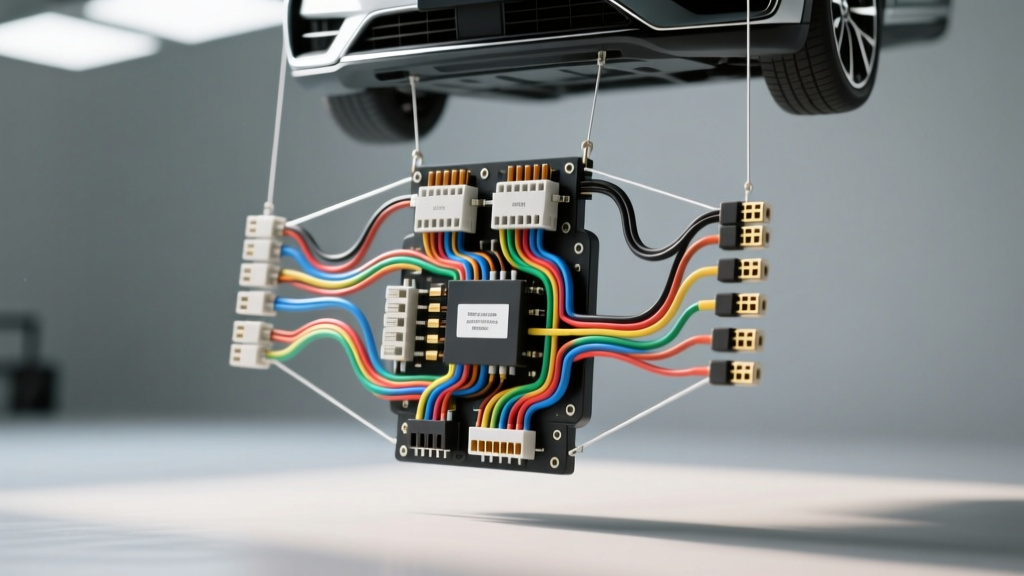
The Critical Flaw in Generic Model-Year Schematics
In modern automotive electrical diagnostics, relying on a generic model-year wiring schematic is a fast track to misdiagnosis, blown modules, and hours of wasted labor. As vehicle architectures have evolved from simple point-to-point wiring to complex, multiplexed CAN bus networks, the physical wiring harness has become highly customized to the exact build configuration of the vehicle. This is why pulling an exact wiring diagram by VIN number is no longer just a best practice—it is an absolute necessity for advanced troubleshooting, upfitting, and module programming.
A generic diagram for a '2019 Silverado 1500' might show a standard 40-pin Engine Control Module (ECM) connector layout. However, if that specific truck was equipped with the 6.2L V8 and the Max Trailering package, the actual harness utilizes a 160-pin Bosch connector with completely different pin assignments for the Dynamic Fuel Management (DFM) solenoids and the Integrated Trailer Brake Controller (ITBC). The 17-digit Vehicle Identification Number (VIN) is the master key that unlocks the exact Bill of Materials (BOM) and corresponding schematic for that specific chassis.
Why You Must Pull a Wiring Diagram by VIN Number
Mid-Year Production Splits and Harness Revisions
Automotive manufacturers frequently implement running changes on the assembly line. A 'Job 1' vehicle built in August might have a completely different body harness than a 'Job 2' vehicle built in March, even though both share the same model year. These mid-year splits are often implemented to address Technical Service Bulletins (TSBs), integrate new supplier components, or comply with updated federal emissions standards. By querying the wiring diagram by VIN number, diagnostic software cross-references the exact build date and sequence number, ensuring you are looking at the correct harness revision. For example, a mid-year revision might move a 120-ohm CAN bus termination resistor from inside the BCM to an inline C305 connector. Using the wrong diagram will lead you to tear apart the dash looking for a resistor that isn't there.
RPO Codes and Option-Specific Pinouts
Regular Production Option (RPO) codes dictate the exact electrical hardware installed at the factory. Let's look at the GM trailering architecture as a prime example. A truck with the standard Z82 trailering package will have a blunt-cut 14 AWG Dark Blue wire under the driver's side dash for the aftermarket brake controller feed. However, if the VIN decodes to the NHT (Max Trailering) RPO code, the vehicle is equipped with an ITBC. In the NHT configuration, that same circuit is routed through the Body Control Module (BCM) and utilizes a 12 AWG wire, completely changing the diagnostic path, the fuse block location, and the pinout at the 7-way RV connector.
Decoding the VIN: From Characters to Connector Pins
To understand how the VIN dictates the wiring diagram, we must break down how specific VIN characters correlate to electrical architecture constraints. While the exact BOM requires a full OEM build-sheet lookup, the VIN itself provides immediate clues regarding major harness variations.
| VIN Position | Attribute | Electrical / Wiring Impact | Connector / Pinout Variation |
|---|---|---|---|
| Character 4 | Vehicle Line / Chassis | Determines main body harness routing and firewall grommet sizes (e.g., standard cab vs. crew cab affects rear body harness length and C-pillar connector types). | Delphi GT 280 series inline connectors vary by pin count. |
| Character 6 | Restraint System / Roof | Dictates the presence of side-curtain airbags and roof-mounted ambient lighting, altering the headliner harness and SDM (Sensing Diagnostic Module) pinouts. | SDM X1/X2 connector pin additions for squib circuits. |
| Character 8 | Engine Type | Determines ECM pinouts, injector driver circuits, and sensor harnesses (e.g., L83 5.3L vs L86 6.2L with AFM/DFM solenoid harness branches). | Bosch 160-pin ECM X1/X2/X3 connector variations. |
| Character 10 | Model Year | Establishes the baseline CAN bus topology (e.g., transition from Low-Speed GMLAN to High-Speed GMLAN or CAN-FD architectures). | DLC (Data Link Connector) Pin 1/2 vs Pin 6/14 assignments. |
Real-World Case Study: GMLAN Topology and the VIN
Consider a scenario where a technician is diagnosing a U0100 (Lost Communication with ECM) code on a late-model GM truck. The technician pulls a generic schematic showing the High-Speed GMLAN bus terminating at the ECM. However, by pulling the exact wiring diagram by VIN number, the technician discovers this specific vehicle was built with a specialized upfit package (RPO code 9B2).
The VIN-specific diagram reveals that the High-Speed GMLAN (500 kbps) does not terminate at the ECM. Instead, the Dark Green (CAN High) and Dark Blue (CAN Low) 18 AWG twisted pair routes through a secondary gateway module located behind the kick panel, utilizing a Delphi Metri-Pack 150 connector. Furthermore, the VIN-specific schematic highlights a splice pack (SP305) that was added to the harness for a secondary PTO (Power Take-Off) controller. Without the VIN-specific diagram, the technician would have wasted hours probing the ECM X1 connector (Pins 42 and 43), completely missing the actual point of failure in the secondary gateway harness.
Step-by-Step: Retrieving and Verifying VIN-Specific Schematics
Accessing the correct data requires using professional-grade diagnostic platforms or OEM portal access. Here is the professional workflow for securing the right schematic:
- Extract the Full VIN: Always pull the VIN directly from the OBD-II DLC or the ECM data stream via a scan tool. Relying on the dashboard sticker or registration can lead to errors if the dash or engine was swapped.
- Query the OEM Build Database: Use platforms like GM Vehicle Information System (VIS), Ford FMCDealer, or Stellantis DealerCONNECT to pull the exact RPO/build sheet. Cross-reference this with your diagnostic software (e.g., Mitchell1 ProDemand, ALLDATA, or Identifix).
- Verify the Harness Part Number: Advanced technicians will locate the physical harness tag (usually a white or black zip-tied tag near the main firewall grommet or under the driver's dash). Match this physical part number to the part number listed in the header of the VIN-specific wiring diagram.
- Check for TSB Supersessions: Even with the correct VIN diagram, always check for wiring-related TSBs. Manufacturers often release 'pigtail' repair kits that change the connector cavity pinout. The OEM service portal will note if a specific TSB overrides the factory schematic for your exact VIN build date.
Common Pitfalls When Ignoring Build Data
Failing to look up the wiring diagram by VIN number leads to catastrophic errors in modern vehicles. One of the most common is the accidental shorting of a 5-Volt Reference Bus. In many modern engine harnesses, a generic diagram might show a 12V switched ignition feed on a specific cavity of the ECM connector. However, a mid-year harness revision for a specific emissions package might have repurposed that exact pin for a 5V reference signal to a new exhaust gas temperature sensor. If a technician uses the generic diagram to test for 12V with a test light, they will instantly backfeed and fry the ECM's internal 5V voltage regulator, resulting in a $1,500+ replacement bill and a bricked vehicle.
Another frequent issue involves airbag (SRS) squib circuits. The resistance and pinout of the steering wheel clock spring connectors change based on whether the VIN indicates a heated steering wheel, a premium audio control stalk, or a specific trim level. Splicing or probing these circuits without the VIN-exact schematic can trigger deployment faults or, worse, accidental airbag deployment.
Authoritative References and Further Reading
For professionals looking to deepen their understanding of vehicle-specific electrical architectures and upfitting guidelines, consult the following authoritative resources:
- GM Upfitter / Body Builder Manuals - Provides exhaustive, VIN-decodable wiring schematics, RPO code breakdowns, and blunt-cut wire locations for commercial and upfit applications.
- SAE International Standards (J1939 / J1979) - The foundational documentation for CAN bus topologies, OBD-II DLC pinout requirements, and multiplexed network protocols that dictate modern harness design.
- Ford Fleet & Body Builder Advisory Service - Offers VIN-specific wiring diagrams, connector cavity charts, and gauge/AWG specifications for Ford, Lincoln, and commercial chassis platforms.
Conclusion
The era of 'close enough' automotive wiring diagnostics is over. Modern vehicles are rolling networks of highly integrated, option-dependent modules. By committing to pulling an exact wiring diagram by VIN number, you eliminate the guesswork, avoid the traps of mid-year production splits, and ensure that every pinout, wire color, and AWG specification you are testing matches the physical copper in the vehicle. Protect your diagnostic accuracy, protect the vehicle's modules, and always let the VIN dictate the schematic.