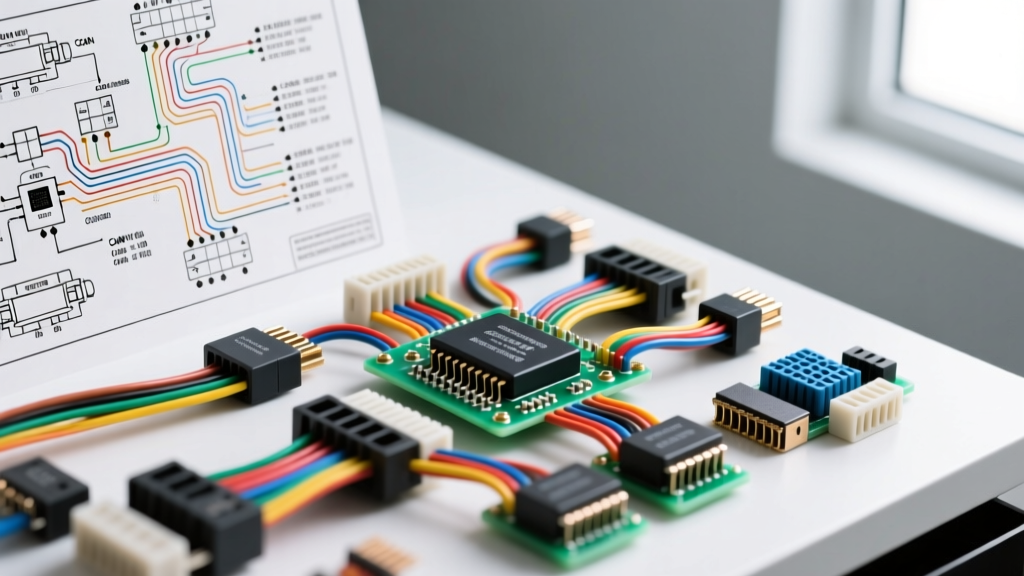
Beyond the Basics: Reading a Modern Car Electrical Circuit Diagram
When master technicians and automotive engineers analyze a modern car electrical circuit diagram, they are no longer looking at simple 12-volt switches, relays, and incandescent bulbs. Today's schematics represent complex multiplexed networks, pulse-width modulated (PWM) drivers, high-speed data buses, and sensitive analog sensor circuits. To properly diagnose drivability faults, parasitic draws, or communication network failures, one must understand the underlying topology of the Powertrain Control Module (PCM) and its associated wiring harness architecture.
This advanced technical deep dive bypasses basic continuity testing and explores the physical layer of automotive wiring. We will deconstruct PCM power distribution matrices, High-Speed CAN (HS-CAN) physical topologies, 5-Volt Reference (VREF) circuits, and the specific American Wire Gauge (AWG) and DIN color code standards required for precision diagnostics.
PCM Power Distribution and Grounding Matrices
The PCM requires multiple distinct power and ground circuits to operate correctly. A common mistake when reading a car electrical circuit diagram is assuming all 'grounds' are equal. In reality, ECU grounds are strictly segregated into Power Grounds and Logic/Sensor Grounds.
Power grounds handle the high-current return paths for internal solenoid drivers, injector peak-and-hold circuits, and ignition coil dwell. These circuits utilize heavy-gauge wiring, typically 10 AWG or 12 AWG, and are bolted directly to the engine block or chassis with strict torque specifications (usually 10-15 Nm) to ensure a zero-resistance path. Logic grounds, conversely, handle milliamperes of current for analog-to-digital (A/D) converters and microprocessor referencing. These use 18 AWG or 20 AWG wire. If a technician accidentally swaps a power ground and a logic ground during a harness repair, the high-current voltage spike will instantly fry the PCM's internal logic traces.
Table 1: Generic Bosch ME7/MED17 PCM Pinout Reference
| Pin | Function | Wire Color (DIN) | AWG Size | Max Allowable Voltage Drop |
|---|---|---|---|---|
| 1 | B+ (Constant Battery) | RT (Red) / WS (White) | 10 AWG | < 0.2V @ 15A |
| 2 | IG1 (Ignition Switched) | SW (Black) / GE (Yellow) | 14 AWG | < 0.1V @ 5A |
| 3 | Main Power Ground | BR (Brown) | 10 AWG | < 0.05V @ 20A |
| 4 | Sensor/Logic Ground | BR (Brown) / WS (White) | 18 AWG | < 0.02V @ 100mA |
| 12 | 5V VREF (Sensor Supply) | GR (Gray) / WS (White) | 20 AWG | N/A (Source) |
Note: DIN 47002 color codes are standard for many European OEMs (e.g., SW=Black, RT=Red, BR=Brown, WS=White, GR=Gray). Always cross-reference the specific OEM wiring manual, as Japanese and American manufacturers often use JASO or SAE J1128 color abbreviations.
High-Speed CAN (HS-CAN) Physical Layer Topology
Modern vehicle networks rely heavily on the Controller Area Network (CAN) protocol, specifically ISO 11898-2 for High-Speed CAN. When tracing a car electrical circuit diagram for a U-code (network communication) fault, you must understand the physical layer of the HS-CAN bus.
The HS-CAN bus utilizes a twisted pair of wires: CAN-High (CAN-H) and CAN-Low (CAN-L). The twisting (typically 20 to 30 twists per meter) is critical for rejecting electromagnetic interference (EMI) from the alternator and ignition coils. The bus requires two 120-ohm termination resistors located at the opposing ends of the network (usually integrated into the PCM and the instrument cluster or ABS module). This yields a total parallel bus resistance of exactly 60 ohms, measured across CAN-H and CAN-L with the battery disconnected.
HS-CAN Dominant and Recessive States
Unlike simple 12V digital signals, CAN bus communication relies on differential voltage. In a Recessive state (logic 1), both CAN-H and CAN-L rest at approximately 2.5V. In a Dominant state (logic 0), the CAN-H transceiver drives its line up to ~3.5V, while CAN-L is pulled down to ~1.5V. The receiving nodes read the 2.0V differential. If a wiring diagram shows CAN-H shorted to ground, the differential voltage collapses, and the entire network segment will fail, logging multiple U-codes across disparate modules.
Table 2: HS-CAN Differential Voltage Diagnostics
| Bus State | CAN-H Voltage | CAN-L Voltage | Differential Voltage | Common Fault Indicator |
|---|---|---|---|---|
| Recessive (Idle) | 2.5V | 2.5V | 0.0V | Normal idle state |
| Dominant (Active) | 3.5V | 1.5V | 2.0V | Normal data transmission |
| CAN-H Short to B+ | 12.0V | 0.0V - 1.5V | > 10.0V | Bus offline, transceiver protection active |
| CAN-L Short to GND | 2.5V - 3.5V | 0.0V | > 2.5V | Asymmetric signal, severe EMI errors |
The 5-Volt Reference (VREF) and Sensor Return Circuits
One of the most misunderstood circuits on any car electrical circuit diagram is the 5-Volt Reference (VREF) bus. The PCM utilizes an internal voltage regulator to step down the 12V battery voltage to a highly stable 5.0V supply. This VREF is shared among multiple critical sensors, including the Manifold Absolute Pressure (MAP) sensor, Throttle Position Sensor (TPS), and Accelerator Pedal Position (APP) sensor.
The VREF circuit is typically wired in a daisy-chain or star topology using 20 AWG wire. Because the sensors draw very little current (usually under 50mA combined), the wire gauge is small. However, if a single sensor on the VREF bus suffers an internal short to ground (or the wiring harness chafes against the engine block), it will pull the entire 5V bus down to 0V. This causes the PCM to lose rationality on all sensors sharing that circuit, often resulting in a 'limp-home' mode. Advanced diagnostics require isolating the VREF circuit at the PCM connector and using a breakout box to measure the internal 5V regulator output before condemning the PCM.
Advanced Troubleshooting: Voltage Drop and Fretting Corrosion
When using a car electrical circuit diagram to diagnose an intermittent fault, the most common error is relying on an ohmmeter for continuity testing. A standard digital multimeter (DMM) uses less than 1 milliamp of current to test continuity. A single strand of 18 AWG copper wire will pass a continuity test with a near-zero ohm reading, even if 90% of the wire's cross-section is severed or corroded. Under a real-world load of 5 amps, that damaged wire will exhibit a massive voltage drop, starving the component of power.
The Dynamic Voltage Drop Test:
Instead of testing resistance, perform a dynamic voltage drop test under load. Connect your DMM in DC Volts across the suspect circuit (e.g., from the battery positive post to the PCM B+ pin) while the circuit is active. According to SAE J1128 standards and general automotive best practices, a voltage drop exceeding 0.1V on a ground circuit or 0.2V on a power feed circuit indicates excessive resistance requiring harness repair.
Terminal Fretting and Micromotion:
Modern vehicles suffer heavily from terminal fretting—a phenomenon where engine vibration causes microscopic movement between the male and female pins inside a connector. This micromotion wears away the tin or gold plating, leading to oxidation and high resistance. When repairing harnesses dictated by the circuit diagram, never reuse a fretted terminal. Always use the OEM-specified crimp tool (e.g., Deutsch DT or TE Superseal) and apply a specialized dielectric grease, such as Nyogel 760G, to dampen vibration and exclude oxygen from the mating surfaces.
Authoritative References and Further Reading
- SAE International - SAE J1128: Low Tension Primary Cable: The definitive standard for automotive wire insulation, temperature ratings, and AWG sizing.
- Bosch Automotive Electrics and Electronics: Comprehensive engineering documentation on vehicle electrical architectures, CAN bus topologies, and ECU hardware design.
- Pico Technology - Automotive Oscilloscope Basics: Industry-leading guides on capturing and analyzing CAN bus physical layer waveforms and PWM injector signals.
Conclusion
Mastering the car electrical circuit diagram requires shifting your mindset from simple 'power and ground' logic to a deep understanding of network topologies, differential signaling, and strict AWG voltage-drop tolerances. By combining schematic literacy with advanced oscilloscope diagnostics and dynamic voltage drop testing, technicians can accurately diagnose complex PCM and CAN bus faults that defy traditional troubleshooting methods.