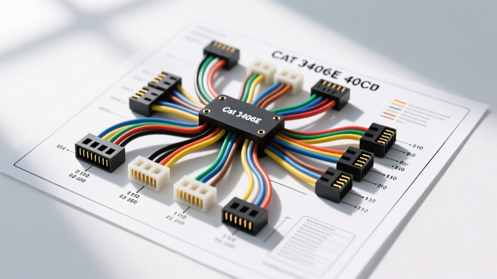
Mastering the Cat 3406E 40-Pin ECM Chassis Harness
When performing a heavy-duty repower, marine conversion, or industrial swap using the legendary Caterpillar 3406E engine, understanding the electrical architecture is non-negotiable. The 3406E utilizes the ADEM II and ADEM III (Advanced Diesel Engine Management) ECM platforms. While the engine-side harness utilizes a 70-pin connector dedicated to injectors, cam/crank sensors, and engine-mounted components, the vehicle-side integration relies on a critical 40-pin chassis connector. This interface handles main power, ignition switching, the J1939 datalink, cruise control, PTO (Power Take-Off), and engine brake solenoids.
While many technicians and fabricators scour the internet for a generic 3406e 40 pin ecm wiring diagram pdf, relying on unverified forum schematics often leads to catastrophic ECM failure, fried datalink transceivers, or parasitic battery draws. This practical how-to guide bridges the gap between factory documentation and real-world repower installation, providing exact Caterpillar wire color codes, AWG specifications, and pinout configurations required to wire the 40-pin chassis connector safely and reliably.
Sourcing Authentic Wiring Documentation
Before cutting a single wire, you must secure accurate documentation. The most reliable sources for the 3406E 40-pin vehicle harness pinout are not generic PDF dumps, but rather OEM-specific body builder manuals and Caterpillar Service Information System (SIS) schematics. For instance, if you are repowering a Peterbilt or Kenworth chassis, the PACCAR Body Builder Manuals provide exact routing, fuse sizing, and bulkhead pinouts that map directly to the Cat 40-pin ECM connector. Always cross-reference your specific ECM serial number prefix (e.g., 1LW, 2WS, 5EK) as ADEM II and ADEM III platforms have slight variations in PTO and engine brake pin assignments.
Essential Tools and Materials for ECM Repowers
Improper crimping is the leading cause of intermittent voltage drops and datalink faults in heavy-duty applications. To execute this installation, you will need:
- Deutsch Crimp Tool: A precision ratcheting crimper calibrated for Deutsch DT/DTM solid and stamped contacts. Refer to the TE Connectivity Deutsch Crimp Specifications for exact die selections.
- Wire Strippers: Calibrated for 18, 14, and 10 AWG to prevent nicking copper strands.
- Heat Shrink & Loom: Adhesive-lined marine-grade heat shrink for all ring terminals and power splices.
- Digital Multimeter (DMM): Capable of measuring millivolt drops and resistance to verify J1939 termination.
- Wedge Locks & Seal Plugs: Never leave an unused cavity in the 40-pin connector empty; always insert a Deutsch seal plug to prevent moisture ingress and subsequent capillary wicking into the ECM.
40-Pin OEM Chassis Connector Pinout Reference Chart
The following table outlines the primary circuits found on the 3406E 40-pin vehicle interface connector. Note that Caterpillar utilizes a standardized wire numbering and color-coding system across its heavy-duty platforms.
| Pin | Circuit Function | Cat Wire # / Color | Min. AWG |
|---|---|---|---|
| 1 | Unswitched Battery (+) | 116 - Red (RD) | 10 AWG |
| 2 | Key Switch Battery (+) | 120 - Blue (BU) | 14 AWG |
| 3 | Main ECM Ground (-) | 118 - Black (BK) | 10 AWG |
| 4 | J1939 Datalink High | 123 - White (WH) | 18 AWG |
| 5 | J1939 Datalink Low | 124 - Green (GN) | 18 AWG |
| 10 | Engine Brake High Stage | 138 - Yellow (YL) | 16 AWG |
| 11 | Engine Brake Low Stage | 139 - Orange (OR) | 16 AWG |
| 19 | Tachometer Output | 153 - Blue (BU) | 18 AWG |
| 20 | Cruise Control Set/Decel | 163 - Purple (PU) | 18 AWG |
| 28 | PTO On/Off Switch | 168 - Gray (GY) | 18 AWG |
| 30 | Check Engine Lamp Driver | 125 - Pink (PK) | 18 AWG |
Step-by-Step 40-Pin Harness Installation Guide
Step 1: Power and Ground Routing (The Foundation)
The ADEM III ECM requires clean, uninterrupted DC voltage to maintain injector timing maps and flash memory. Pin 1 (116-RD) must be routed directly to the battery positive terminal or a dedicated, fused mega-fuse distribution block. Use a minimum of 10 AWG stranded copper wire. Do not route this through a chassis ignition switch; this pin keeps the ECM alive for datalink communication and post-run coolant fan cycling.
Pin 3 (118-BK) is the main ECM ground. This must be terminated to a clean, bare-metal chassis ground stud or directly to the battery negative terminal. Torque the ground ring terminal to 12-15 Nm (106-132 lb-in). A poor ground will cause the ECM to seek a ground path through the J1939 datalink shield, instantly frying the internal communication chip.
Step 2: Ignition and Key Switch Integration
Pin 2 (120-BU) is the switched ignition feed. This wire tells the ECM to wake up and begin the pre-injection sequence. Route this through a heavy-duty ignition relay triggered by the cab key switch. Use 14 AWG wire. Incorporate a 10-amp inline blade fuse within 12 inches of the relay output to protect the ECM's internal ignition trace from short circuits.
Step 3: J1939 Datalink and Sensor Wiring
The SAE J1939 datalink is the backbone of modern heavy-duty communication, linking the 3406E ECM to the transmission TCM, ABS module, and cab dash cluster. Pin 4 (123-WH) is J1939 High (CAN-H) and Pin 5 (124-GN) is J1939 Low (CAN-L). According to SAE J1939 Datalink Standards, these two wires must be a twisted pair with 3 to 4 twists per inch to reject electromagnetic interference (EMI) from the alternator and injector solenoids. Use 18 AWG wire. Furthermore, the datalink requires exactly two 120-ohm terminating resistors on the network—one typically located inside the ECM, and the other at the opposing end of the chassis harness. Measure between Pin 4 and Pin 5 with the batteries disconnected; your DMM should read exactly 60 ohms.
Step 4: Engine Brake and PTO Configuration
If your repower utilizes a Jacobs compression release engine brake, wire the cab toggle switches to Pin 10 (High Stage) and Pin 11 (Low Stage). These circuits are ground-triggered by the ECM or switch-triggered depending on the exact harness configuration; verify your specific schematic before applying 12V to these pins, as feeding battery voltage into a ground-switch return will short the ECM driver. For PTO applications, Pin 28 requires a momentary ground signal to engage the remote throttle and governor parameters programmed into Cat ET (Electronic Technician).
Common Wiring Failure Modes and Troubleshooting
Even with a perfect physical installation, environmental factors and vibration can introduce faults. Use Cat ET or a diagnostic adapter to monitor the following common CID (Component Identifier) and FMI (Failure Mode Identifier) codes related to the 40-pin harness:
- CID 0248 FMI 02 (J1939 Datalink Erratic): Usually caused by a missing 120-ohm terminator, corroded Deutsch pins on Pin 4/5, or untwisted datalink wires picking up alternator whine.
- CID 0041 FMI 03 (Sensor Supply Voltage High): Often indicates that the main ECM ground (Pin 3, 118-BK) has loosened, causing the ECM to float above chassis ground potential. Check voltage drop across the ground cable under cranking load; it should not exceed 0.1V.
- CID 0190 FMI 02 (Engine Speed Erratic): While this points to the engine-side harness, severe voltage drops on the 40-pin switched ignition circuit (Pin 2) during starter engagement can cause the ECM to momentarily brown-out and lose the cam/crank sync signal.
Final Torque and Sealing Verification
Once all 40 pins are populated (or sealed with blank plugs), ensure the connector coupling ring is threaded completely and the secondary locking tab engages with an audible click. Apply a thin layer of dielectric grease to the outer seal ring before mating to prevent moisture intrusion. By adhering strictly to these AWG ratings, Cat color codes, and crimp standards, your 3406E repower will deliver the same bulletproof reliability as a factory-installed heavy-duty configuration.