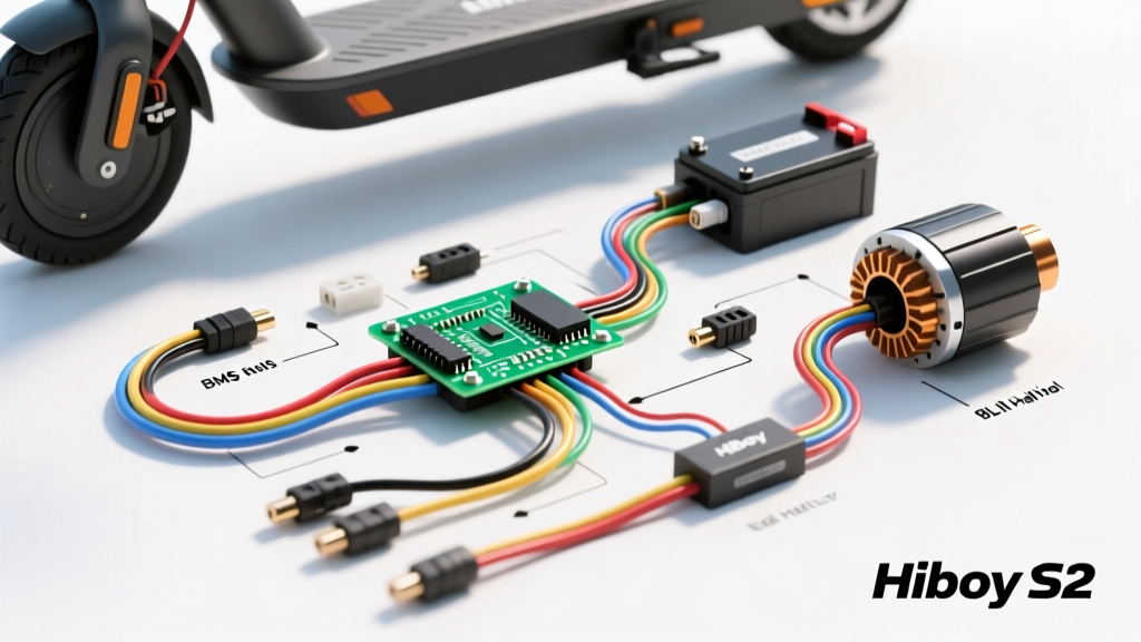
Introduction to the Hiboy S2 Electrical Architecture
Many technicians, DIY repair enthusiasts, and fleet maintainers search for a Hiboy S2 wiring diagram PDF, only to find that original equipment manufacturer (OEM) service manuals for light electric vehicles (LEVs) are rarely published to the public. Unlike traditional automotive wiring schematics found in Haynes or Chilton manuals, e-scooter electrical architectures rely on proprietary, sealed harnesses and generic Chinese Electronic Speed Controllers (ESCs). However, understanding the underlying electrical topology of the Hiboy S2 is critical for diagnosing throttle lag, display blanking, and motor stuttering.
This comprehensive wiring walkthrough serves as your definitive textual wiring diagram. We will dissect the 36V nominal (42V peak) power delivery system, map the ESC pinouts, and detail the Brushless DC (BLDC) hub motor phase and hall sensor configurations. Whether you are replacing a blown MOSFET in the controller or troubleshooting a water-damaged Higo connector, this guide provides the exact wire colors, AWG ratings, and voltage specifications required for accurate diagnostics.
High-Voltage DC Power Delivery & Battery BMS
The heart of the Hiboy S2 is its 36V 7.5Ah lithium-ion battery pack, configured in a 10S3P (10 series, 3 parallel) arrangement using 18650 cells. The main power exits the battery enclosure via a heavy-duty XT60 anti-spark connector. Understanding the BMS (Battery Management System) output is the first step in any electrical diagnosis.
- Main Positive (B+): 12 AWG Red Silicone Wire. Carries up to 15A continuous, 20A peak. Voltage ranges from 30V (cutoff) to 42V (fully charged).
- Main Negative (B-): 12 AWG Black Silicone Wire. Routes directly to the ESC ground plane and the negative terminals of the main filter capacitors.
- Charge Port (C+ / C-): 14 AWG wires routing to the GX12-3P or DC barrel charge port. The BMS actively monitors cell balancing during the charging cycle.
Safety Warning: Before disconnecting the XT60 connector to access the ESC, always discharge the main filter capacitors (typically 470µF 63V electrolytic capacitors) using a 100-ohm 5W power resistor. A direct short with a screwdriver can weld metal and destroy the ESC's main power traces.
Hiboy S2 ESC Pinout & Wire Color Codes
The Hiboy S2 utilizes a 36V 15A sine-wave or square-wave ESC (often manufactured by KingMotor or similar LEV suppliers). The main harness breaks out into several waterproof JST-SM and Higo connectors. Below is the definitive pinout table for the low-voltage control harness.
| Connector Type | Function | Wire Colors | Voltage / Signal Spec |
|---|---|---|---|
| 3-Pin JST-SM | Throttle Input | Red, Black, Green | Red: 5V | Black: GND | Green: 0.8V (idle) to 3.6V (full) |
| 4-Pin Higo | Display / UART | Red, Black, Blue, Yellow | Red: 5V | Black: GND | Blue: TX | Yellow: RX |
| 5-Pin Higo | Motor Hall Sensors | Red, Black, Yellow, Green, Blue | Red: 5V | Black: GND | Y/G/B: 0-5V Square Wave |
| 2-Pin JST | Electronic Brake / E-ABS | White, Black | Normally Open (NO) switch circuit. Pull to GND to engage. |
| 2-Pin JST | Headlight Power | Yellow, Black | Switched 36V-42V DC (Steps down at the LED driver) |
For deeper insights into lithium-ion BMS behavior and how cell imbalance affects ESC voltage cutoff thresholds, refer to the extensive testing data published by Battery University. A failing BMS will often mimic a dead ESC by prematurely dropping voltage under the 15A load of the Hiboy S2's 350W motor.
BLDC Hub Motor: Phase & Hall Sensor Mapping
The rear hub motor is a 350W Brushless DC (BLDC) unit. It requires two distinct harnesses: the high-current phase wires and the low-voltage hall sensor feedback loop. Miswiring these during a motor replacement will instantly blow the ESC's MOSFETs or cause the motor to lock up and overheat.
Phase Wires (High Current)
The phase wires are 14 AWG silicone wires terminating in 4mm bullet connectors. They carry the 3-phase alternating current generated by the ESC's MOSFET bridge.
- Phase A: Yellow
- Phase B: Green
- Phase C: Blue
Troubleshooting Tip: If the motor stutters or draws excessive current without moving, the phase sequence is incorrect. You must swap two phase wires (e.g., Yellow and Green) and simultaneously swap their corresponding Hall Sensor signal wires to realign the rotor position feedback.
Hall Sensors (Rotor Position Feedback)
Inside the motor stator, three linear Hall effect sensors (typically Honeywell SS41 or similar) detect the magnetic poles of the rotor magnets. They operate on 5V DC supplied by the ESC. According to SAE J1113 standards for electrical component testing, hall sensor circuits are highly susceptible to Electromagnetic Interference (EMI) from the high-current phase wires. If your Hiboy S2 experiences random error codes on the display, check that the hall sensor shield wire (if present) is properly grounded to the ESC chassis, and ensure the 5-pin connector is free of dielectric grease contamination.
Step-by-Step Multimeter Diagnostics
When you lack a physical wiring diagram PDF, a digital multimeter (DMM) is your best tool for mapping the Hiboy S2 harness. Follow this diagnostic sequence to isolate faults:
- Verify BMS Output: Set DMM to DC Voltage. Probe the XT60 connector. A reading below 30V indicates a tripped BMS or severely depleted cells. A reading of 42V confirms a healthy pack.
- Test 5V Regulator: Turn the scooter on. Probe the Red and Black wires on the disconnected Throttle connector. You must read exactly 5.0V (+/- 0.2V). If you read 0V, the ESC's internal 78L05 voltage regulator has failed, and the ESC must be replaced.
- Throttle Signal Sweep: Back-probe the Green throttle signal wire while slowly depressing the thumb throttle. The voltage should climb linearly from 0.8V to 3.6V. Any sudden drops to 0V indicate a worn potentiometer or damaged magnet inside the throttle housing.
- Phase Wire Continuity: With the battery disconnected, set the DMM to resistance (Ohms). Measure between the motor phase wires (Yellow-Green, Green-Blue, Blue-Yellow). You should see a very low, balanced resistance (typically under 1.0 ohm). An 'OL' (Open Line) reading indicates a broken internal stator winding.
Connector Types & Waterproofing Standards
The Hiboy S2 relies heavily on Higo (Julet) waterproof connectors for exterior routing and standard JST-SM connectors for internal ESC routing. The Higo connectors feature an IP67 rating and utilize rubber O-rings to prevent water ingress. However, the capillary action of stranded wire can wick water directly into the ESC if the wire insulation is nicked near the connector. When repairing a harness, always use adhesive-lined marine-grade heat shrink tubing to seal the wire entry point, preventing catastrophic ESC corrosion. For further reading on LEV electrical safety and connector degradation, resources from the SAE International electromagnetic compatibility guidelines highlight the necessity of maintaining sealed grounds in high-vibration environments like e-scooter rear swingarms.
Summary
While a factory-issued Hiboy S2 wiring diagram PDF may not exist in the public domain, the electrical principles governing its 36V ESC, BMS, and BLDC motor are universal. By understanding the specific wire color codes, AWG requirements, and voltage thresholds outlined in this walkthrough, you can confidently diagnose, repair, and maintain the electrical system of your vehicle without relying on guesswork. Always prioritize safety by disconnecting the main power and discharging capacitors before probing the ESC harness.