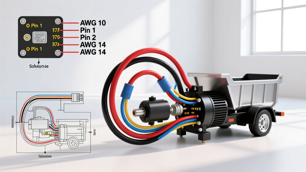
Introduction to Hydraulic Dump Trailer Wiring
When towing a hydraulic dump trailer, the electrical demands far exceed those of a standard flatbed or utility trailer. The most critical mistake beginners make is attempting to power the 12V DC hydraulic pump motor directly through the standard 7-way RV connector. Hydraulic pump motors (such as those manufactured by MTEC or Monroe) typically draw between 150 and 300 amps under peak load. Running this amperage through a standard trailer plug will instantly melt the wiring harness and create a severe fire hazard.
To safely operate your equipment, the correct wiring diagram for hydraulic dump trailer setups relies on an onboard, dedicated 12V deep-cycle or AGM battery mounted on the trailer tongue. The tow vehicle’s electrical system is only responsible for charging this battery and operating the trailer lights and brakes, while a heavy-duty continuous solenoid handles the massive current required to lift the bed. This beginner-friendly guide breaks down the exact wire colors, AWG sizes, and pin configurations you need to wire your dump trailer safely and reliably.
The 7-Way RV Connector: Your Power Foundation
The foundation of your trailer’s electrical system is the 7-way RV blade connector, standardized under SAE J286 Trailer Connector specifications. Understanding the pinout is essential before you begin routing wires along the trailer frame.
| Pin Position | Function | Standard Wire Color | Recommended AWG |
|---|---|---|---|
| 1 (Center) | Ground (Chassis) | White | 8 AWG |
| 2 | Electric Brakes | Blue | 10 AWG |
| 3 | Tail / Running Lights | Brown | 14 AWG |
| 4 | 12V Auxiliary (Battery Charge) | Black | 10 AWG (or 8 AWG) |
| 5 | Right Turn / Stop | Green | 14 AWG |
| 6 | Left Turn / Stop | Red | 14 AWG |
| 7 | Reverse / Auxiliary Lockout | Yellow | 14 AWG |
Note: For dump trailers, the Black wire (Pin 4) is the most important circuit. It supplies a constant 12V charge from the tow vehicle’s alternator to the trailer’s onboard battery. Upgrading this specific circuit to 8 AWG wire is highly recommended to minimize voltage drop over the 20-foot length of the trailer tongue.
The Hydraulic Pump Motor Circuit Explained
Because the hydraulic pump requires massive amperage, it must be wired directly to the trailer-mounted battery using heavy-gauge battery cable. The circuit is controlled by a Continuous Duty Solenoid (often a Trombetta or Cole Hersee relay). Unlike a standard automotive starter solenoid, which is designed for brief engagement, a continuous duty solenoid can remain energized for the 30 to 60 seconds required to fully raise a loaded dump bed without overheating.
Continuous Duty Solenoid Pinout and Wiring
Most heavy-duty dump trailer solenoids feature four terminals: two large threaded studs for the high-amperage load, and two small spade or screw terminals for the low-amperage trigger circuit.
| Terminal | Connection Point | Wire Size | Function |
|---|---|---|---|
| Large Stud A | Trailer Battery Positive (+) | 4 AWG or 2 AWG | Main power input |
| Large Stud B | Hydraulic Pump Motor (+) | 4 AWG or 2 AWG | Main power output |
| Small Spade 1 | Cab Switch / Up-Down Switch | 14 AWG | 12V Trigger signal |
| Small Spade 2 | Trailer Frame Ground | 14 AWG | Completes trigger circuit |
According to Texas Industrial Electric relay guidelines, ensuring the small trigger ground has a clean, bare-metal connection to the frame is vital. A weak trigger ground will cause the solenoid to chatter or fail to close the high-amp contacts entirely.
Step-by-Step Wiring Walkthrough
- Mount the Battery and Solenoid: Secure the 12V deep-cycle battery in a ventilated, weather-resistant box on the trailer tongue. Mount the continuous duty solenoid as close to the battery positive terminal as possible to reduce the length of the unprotected, always-hot 4 AWG cable.
- Wire the High-Amp Circuit: Connect a 4 AWG red battery cable from the battery positive terminal to Large Stud A on the solenoid. Connect another 4 AWG cable from Large Stud B to the positive terminal on the hydraulic pump motor.
- Establish the Motor Ground: Do not rely on the hydraulic fluid lines or pivot hinges for grounding. Run a dedicated 4 AWG black cable from the pump motor’s negative terminal directly to the trailer battery’s negative terminal or a dedicated, sanded grounding bolt on the main frame rail.
- Wire the Trigger Switch: Run a 14 AWG wire from a fused 12V source (or a dedicated toggle switch wired to the battery) to Small Spade 1 on the solenoid. Ground Small Spade 2 to the trailer frame.
- Connect the 7-Way Charging Circuit: Run the Black wire (Pin 4) from the 7-way plug through a 40-amp circuit breaker, then attach it to the positive terminal of the trailer battery. This allows the tow vehicle to maintain the battery charge while driving.
- Install the Breakaway Switch: Wire the breakaway switch in-line between the trailer battery positive and the Blue wire (Pin 2) for the electric brakes. If the trailer detaches, the pin pulls, sending 12V directly to the brakes to stop the trailer.
Troubleshooting Common Failure Modes
Even with a correct wiring diagram for hydraulic dump trailer systems, environmental factors and heavy use can lead to electrical faults. Use this diagnostic tree to solve common issues:
- Symptom: Solenoid clicks loudly, but the hydraulic pump does not turn, or the bed only lifts when empty.
Cause: Severe voltage drop or high-resistance ground.
Fix: Inspect the 4 AWG ground wire. Use a multimeter to check for voltage drop across the ground cable while the switch is engaged. If you read more than 0.2V, sand the frame contact point down to bare metal and apply dielectric grease. - Symptom: Trailer battery drains completely while parked or disconnected from the tow vehicle.
Cause: Missing isolation diode or a stuck solenoid contact.
Fix: If the 7-way Black wire is connected directly to the battery without a 40A auto-reset breaker or isolation diode, reverse current can drain the battery into the tow vehicle’s electronics. Additionally, tap the solenoid casing with a rubber mallet; if it is mechanically stuck closed, it will drain the battery continuously. Replace the solenoid if this occurs. - Symptom: Pump motor runs continuously and will not shut off when the switch is released.
Cause: Welded solenoid contacts due to excessive arcing.
Fix: The motor is drawing too many amps, melting the internal copper contacts of the solenoid together. Immediately disconnect the battery. You must replace the solenoid and investigate the hydraulic pump for mechanical binding or low fluid levels causing the motor to over-amp.
Authoritative References
For further reading on heavy-duty trailer electrical standards, consult the etrailer.com Wiring FAQ for visual 7-way pinout diagrams and routing best practices. Always ensure your wire gauges and circuit breakers comply with SAE and DOT regulations for the specific GVWR of your dump trailer.